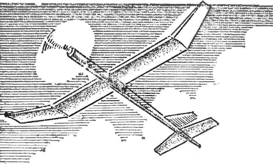
 Not everyone can use the balsa when building models. Not everywhere is the enamel and long-fibre paper, stitched. That’s why modelers are constantly looking for new more affordable alternatives. We offer rezinomotornaya model of foam by weight, durability and flight characteristics are not inferior designs made of balsa, and in some ways even surpasses them. Some days it can make any novice an aeromodeller.
The model is very sensitive to regulation and changing the angle of the rudder well withstand dynamic load in case of unsuccessful start. At the same time when chrapanie and transportation to be handled especially carefully, trying not to dent the foam parts.
The main material is foam PS-4. It is durable, has a low density of 0.035—0.08 g/cm3 (the density of the balsa 0.1—0.2 g/cm3), easy to cut with a knife, saw, polished with sandpaper. In the construction used traditional materials such as pine, Linden.
The FUSELAGE (Fig. 1) consists of two parts: the motor and tail. The motor part is made of two closely fitting bars foam. On the inner side along each bar with a pencil, apply two lines for the size of the inner diameter of the fuselage, and at the end draw a semicircle of the same diameter. With a sharp knife cut the bars from the extra foam. Then sand paper mounted on a round rod slightly smaller diameter than the interior of the fuselage, wing half to the desired size. In the same way make the second part and the motor part.
Before connecting them, make the tube of two layers of construction paper with a length of 80 mm. the Diameter should be 0.5—1 mm smaller than the inner diameter of the fuselage Tube, lubricated with the glue BF-2, paste to the front of one of the halves. It is necessary to increase the rigidity of the front, the most critical component. Fluff the joints with glue, attach the second half of the motor part. Then fix them with pins and secure with tape. After the glue has set, approximately 24 hours, remove the tape and the knife give the fuselage a rounded shape. Final processing run the sandpaper, first coarse sanding, then fine.
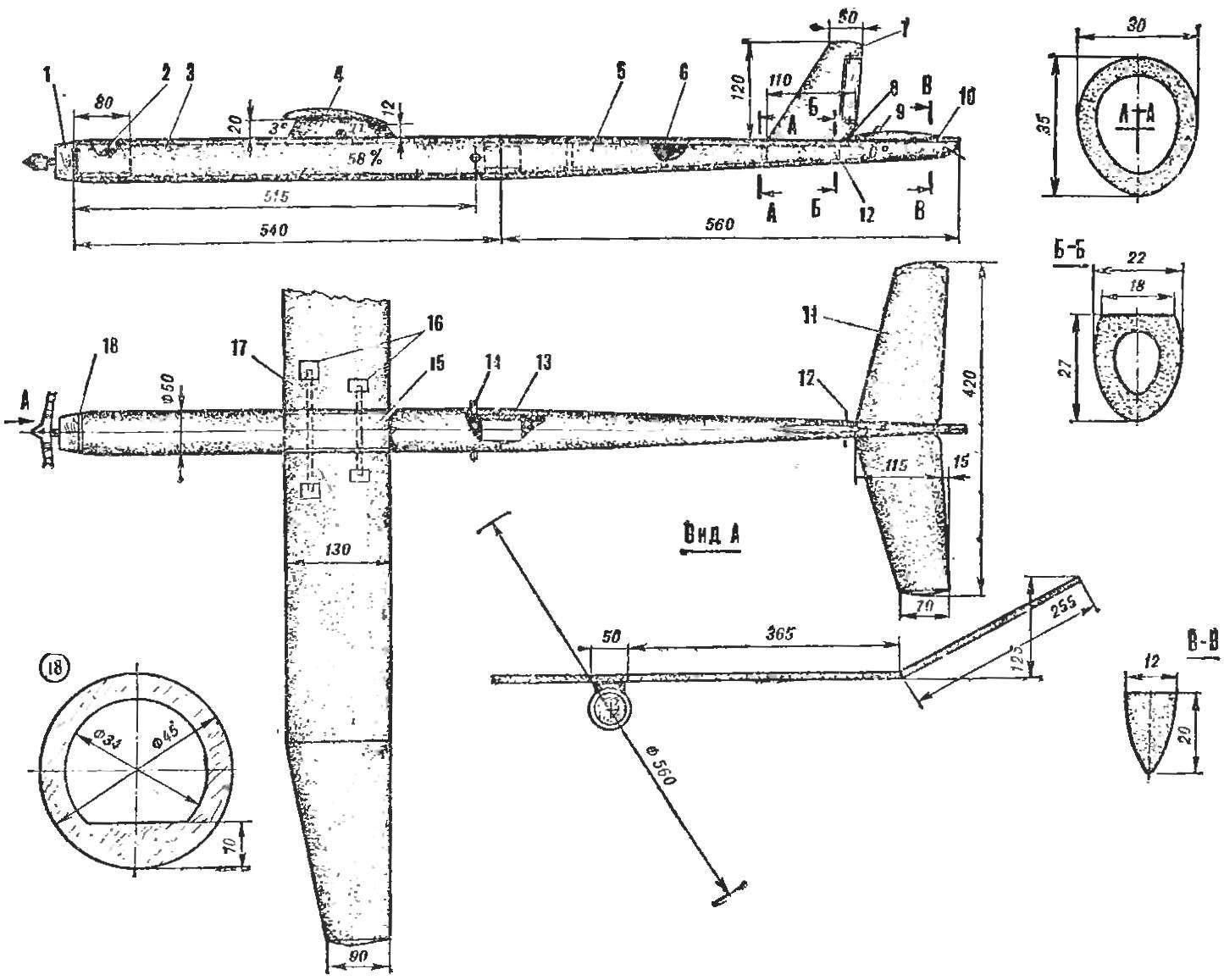
Fig. 1. General view of the model:
1 — boss, 2 — tube (paper), 3 — the engine part of the fuselage, 4 — pole, 5 — aft fuselage, 6 — frame (foam), 7 — Kiel, 8 — emphasis of the stabilizer, 9 — ledge for fastening tightening gum, 10 — determinator, 11 — stabilizer 12 — pin for fastening tightening gum, 13 — Bush (foam), 14 — a tube (made of anodized aluminum Ø 6X60), 15 — center, 16 — boss 17 — console 18 — thrust washer (plywood 1.5 mm).
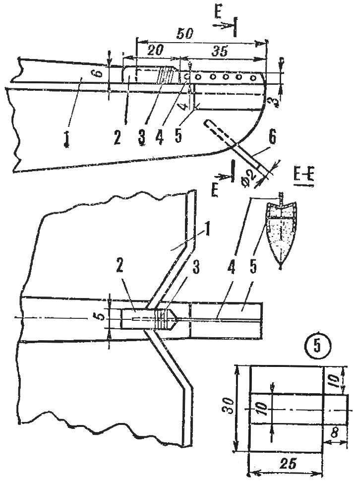
Fig. 2. Device determinator:
1 — the stabilizer, 2 — pad mounting plates determinator (Linden), 3 — threads with glue, 4 — determinator plate (aluminum 0.5 mm) 5 — screen-stand of determinator (0.4 mm aluminum), 6 — pin for rubber, securing the plate determinator and the fuse on the screen-the stand (bamboo Ø 2 mm).
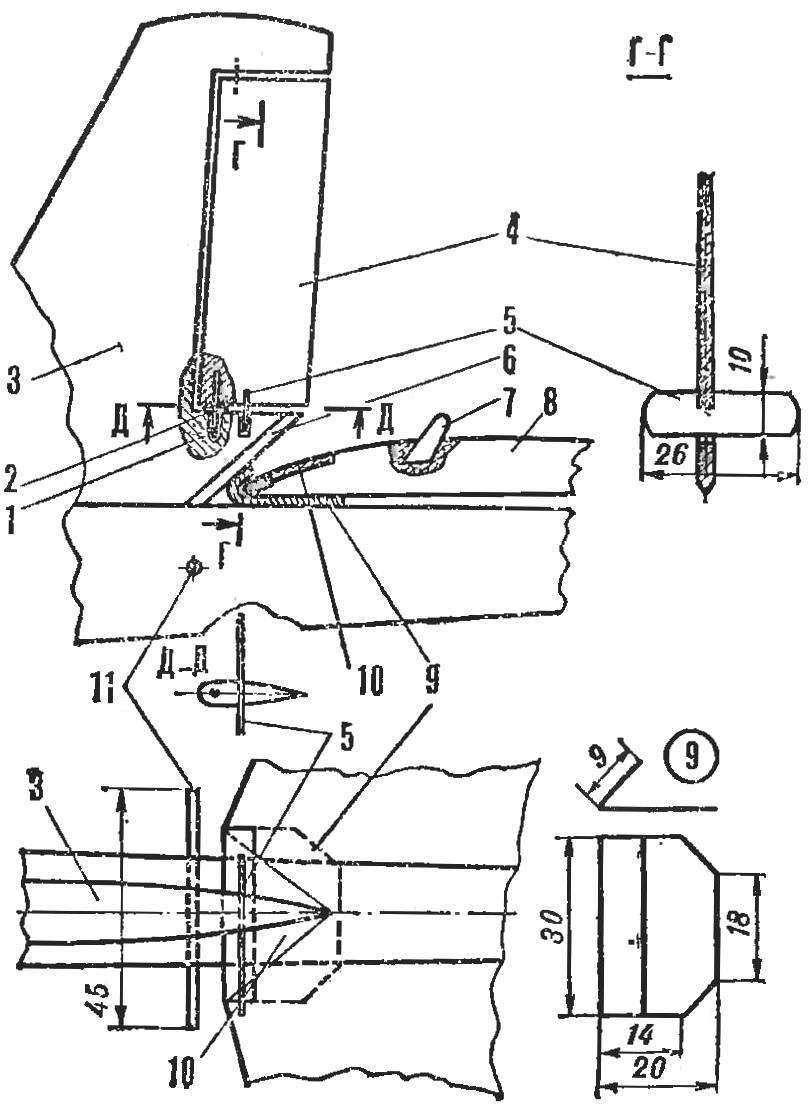
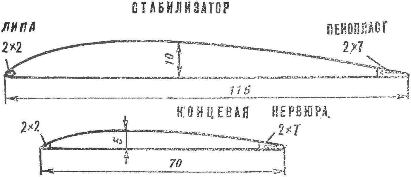
Fig. 3. The emphasis of the stabilizer and the device for fixing of the rudder:
1 — axis (sticker in the wheel turning freely in the bottom of the keel), 2 — washer (celluloid), 3 — keel, 4 — rudder, 5 — plate, limiting the deflection of the rudder (celluloid 0.5 mm, is glued into the rudder, tightly slides in the slot of the bottom of the keel), 6 — rake (lime 2X1,5 mm), 7 — lug for fastening tightening gum (celluloid 0.5 mm), 8 — regulator, 9 — emphasis of the stabilizer (celluloid 1 mm), 10 — veneer (Linden 0.5 mm), 11 — pin for fastening tightening gum (bamboo Ø 2 mm).
To the front of the motor part to glue the thrust washer, cut to the shape of the fuselage made of plywood with a thickness of 1,5 mm. In it insert the lug of the screw motor.
It should be borne in mind that it is necessary to use glue BF-2, PVA, high-grade (thick) casein, epoxy resins. Enamel, polyester resin and other glues that contain acetone, can not be used, as they dissolve the foam.
At the other end of the motor side drill two holes and put them in a sleeve made from strips of drawing paper with a width of 6 mm. is inserted Into them dural tube for attaching the rubber motor.
The tail motor is made similarly with the difference that inside the foam is selected on the cone and the walls are more subtle. Before gluing in the internal cavity of 100-150 mm foam insert frames with a thickness of 8-10 mm; they give the construction more stiffness. To the rear attach the keel, walkera stabilizer and determinator. Foam manufacture the hollow sleeve, which snugly fit in the tail and motor parts for more durable fixing. The junction of the trim flush with sandpaper.
Engine part fit an a nylon ribbon or thin fiberglass, top it promazhte glue BF-2. After 1— 2 hours, when the glue dries, close-fitting iron warm iron 40-50° to remove the blisters. Then glue the motor and the tail part of the fuselage.
WING (Fig. 4) consists of a center section and two consoles. Fabricate the center section of the SS-4, and lightweight inside the pylon where it attaches to the fuselage — from the more dense foam. On both sides of the center section glue the rib of 1.5 mm thickness with holes for the pins. In the center section glue joint will fix dural and bamboo pins for fixing consoles. Putting on the fuselage skins, wing pylon at the place of installation. The pylon with the center wing after centering the model attach to the fuselage glue the dowel pins Ø 2 mm.
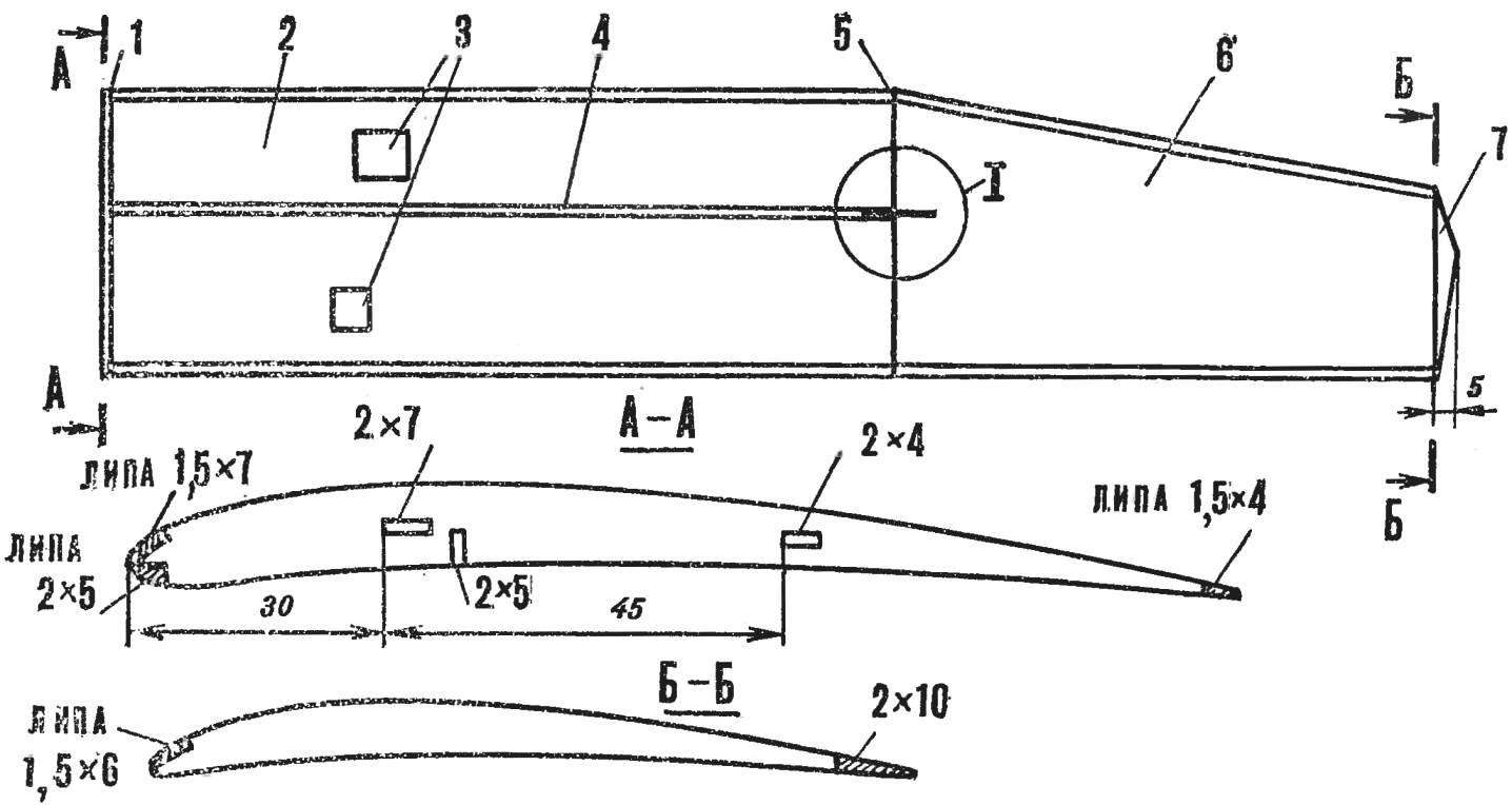
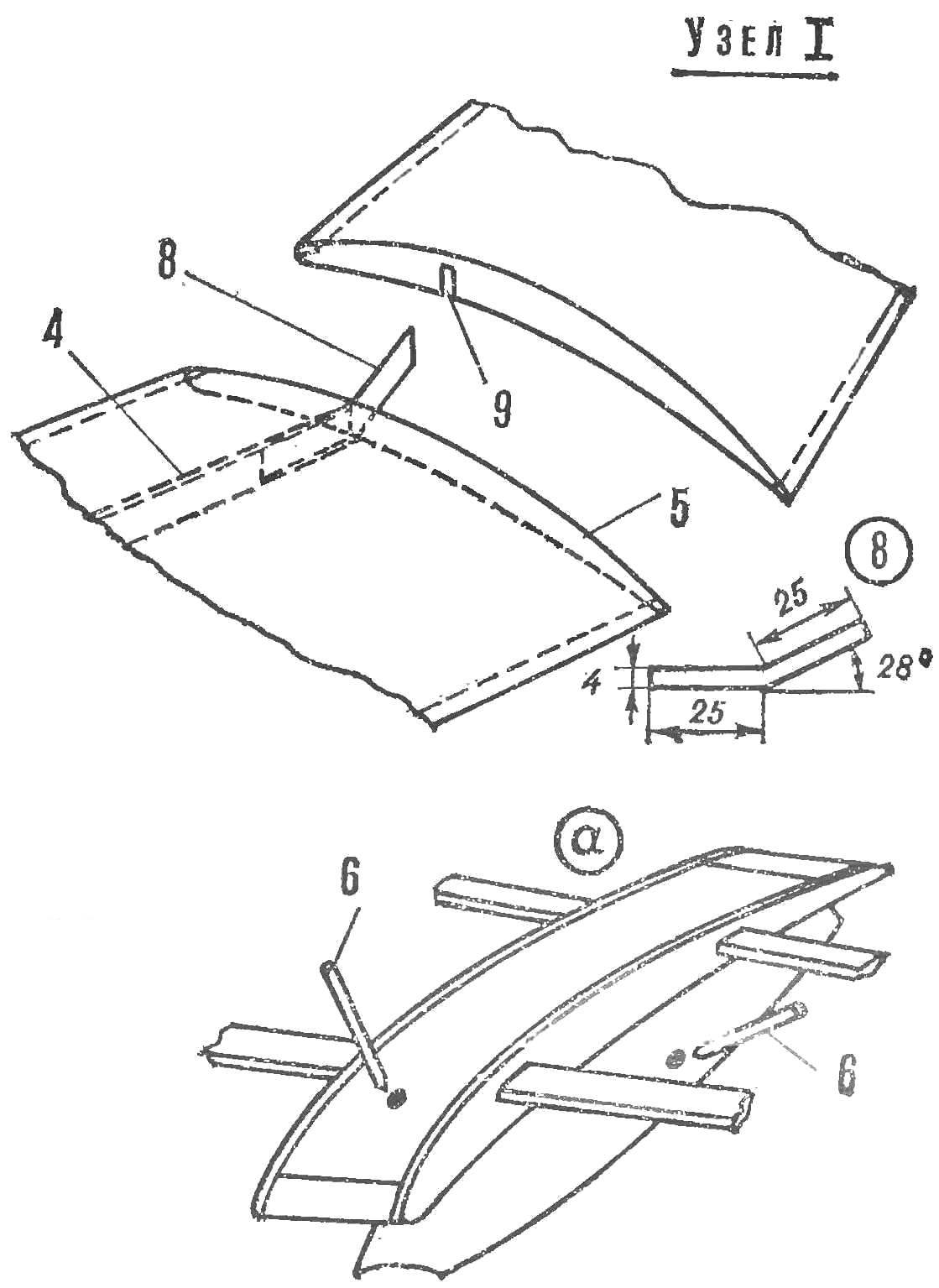
Fig. 4. Wing:
1 — root rib (plywood 1.5 mm), 2 — console, 3 — boss, 4 — spar (pine 2X5 mm), 5 — rib console (Linden 1.5 mm), 6 — terminal part of the console, 7 — rib end, the 8 — gon (aluminum 0.3 mm), 9 — a slot for sticking a square.
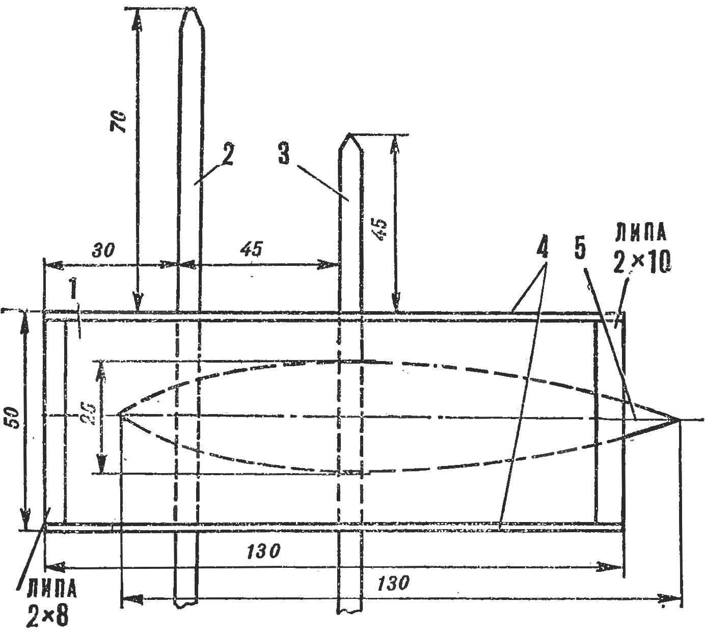
Fig. 5. Pylon center section:
1 — center, 2 — pin (2X7 mm aluminum), 3 — Shire (bamboo 2X4 mm), 4 — rib center section (plywood 1.5 mm), 5 — pole, 6 — pin (pine Ø 2 mm), a — mount cataplana to pylon and pylon to the fuselage.
Cut Styrofoam plates the size of each part of consoles. To them the ends of the ribs attach. With a knife and sandpaper, pretreat the plane of the wing to the profile ribs. In the middle part with a hacksaw, saw a groove for the spar, cut the grooves on the front edge for bonding strips of lime, slightly trim the rear edge and stick a piece of denser foam or lime. Then sharpened metal plate from the side of the root ribs make two holes for fastening consoles to the center section. Where the end pins in the consoles provide cutouts for sticking bosses from the more dense foam When the glue is dry, sandpaper “adjust” the profile of the wing and sand.
End of the console is also made of foam, but without the spar.
End ribs and the trailing edge, take a thick foam or lime. Console obtyanite nylon ribbon, as described above, and seal it with end parts which can not be covered. The connection optionally, glue a strip of tissue paper.
STABILIZER — aslangirey, has a PLANO-convex profile. The front edge of Linden, rear and ending — of a more dense foam. The profile of the stabilizer carved pattern. Shank for determinator glue on the middle chord.
KEEL — aslangirey, lenticular. Front edge and a rudder of dense foam. Steering wheel clip on bamboo axes Ø 1 mm.
The SCREW (Fig. 6) Ø 560 mm thickened blade profile made of solid dense foam (the same technology that of wood). In the root of each blade with a hacksaw, saw through the groove and glue the plywood plate with thickness of 1.5 mm. In these places the blade glue a nylon ribbon, and then both sides stick plates of celluloid of a thickness of 0,5 mm.
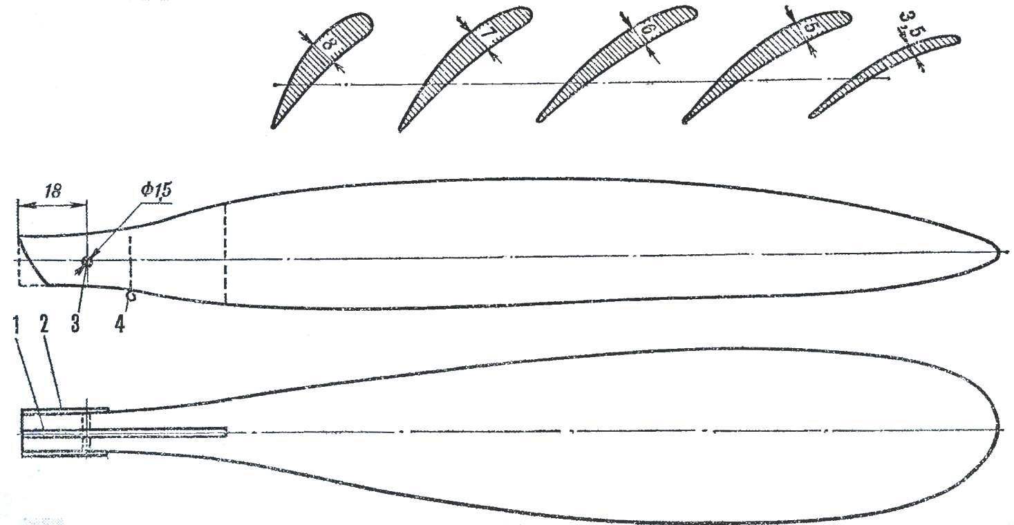
Fig. 6. Screw:
1 — plate (plywood 1.5 mm), 2 — cheeks (celluloid 0.5 mm), 3 — hole for axle, 4 — pin for fastening elastic bands, tightening of the blade.
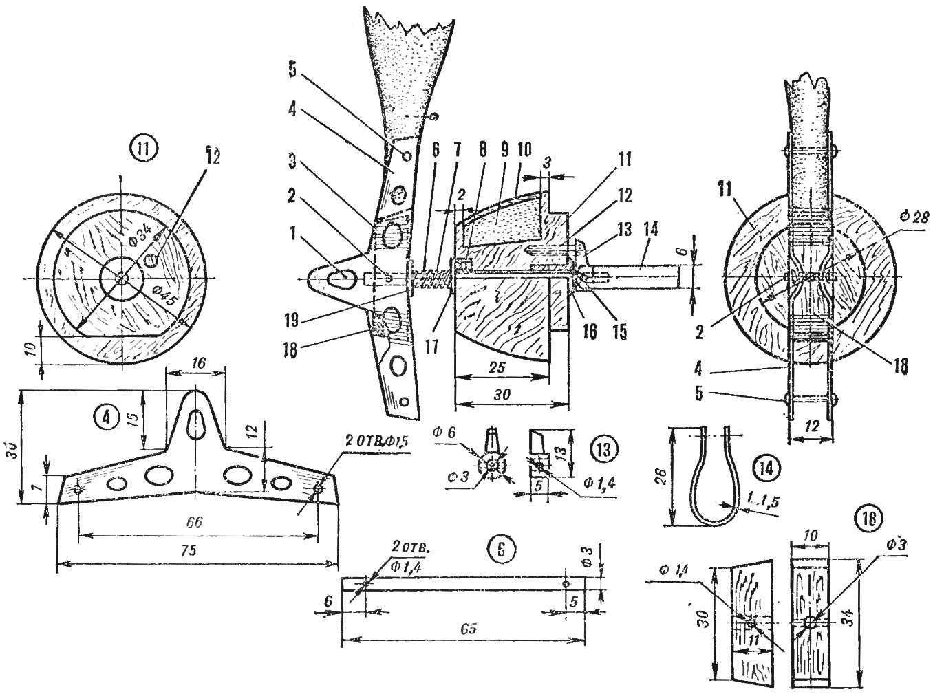
Fig. 7. Hub, the lug and retainer:
1 — hole twist the rubber motor, 2 — stud mounting vnta the hub to the axle (steel Ø 1,4) 3 — threads with glue, 4 — hub (made of anodized aluminum 1 mm), 5 — axis propeller blade (made of anodized aluminum Ø 1.5 mm), 6 — axis (wire OVS Ø 3X65 mm), 7 — retaining spring (wire Ø 0.3 — 0.4 mm), 8 — bearing 10X4, 9 — foam, 10 top finish (veneer, basswood thickness of 1 mm), 11 — boss (lime), 12 — screw (M3), 13 —retaining bushing (silumin), 14 — earring to rubber motor (aluminum 1-1. 5 mm), 15 — pin for attaching earrings locking sleeve (steel Ø 1.4 mm), 16 — bushing for the axle (aluminum), 17 — thrust washer (steel 0,5 mm), 18 insert (beech), 19 — thrust washer (steel Ø 10X1 mm).
The design of the hub, lugs and retainer shown in figure 7.
BRIEF TECHNICAL CHARACTERISTICS
Area, dm2:
wing……………………………………………15,1
stabilizer……………………………….3,86
Weight, g:
the fuselage pylon………………………77
wing……………………………………………80
stabilizer………………………………..10
the screw boss……………………………41
the rubber motor (round rubber)……40
A. DUBOVIK
Recommend to read
 CUT THE TILE
When carrying out cladding work, tiles is often a need to cut from it a narrow strip. To do this, of course, can and glass cutter, but it is difficult, and there is no guarantee that the... CAR TO GIVE
Under this title in the "photo stitch" ("modelist-Konstruktor" No. 2'93) was first published information about my home — country car. Since then, the mail never ceased wearing me...
