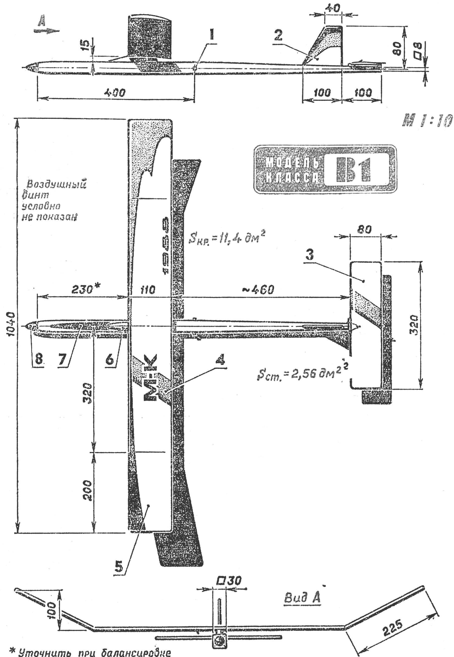
The design of the wing and stabilizer rezinomotornaya repeats the version used on the airframe. The only difference is the absence of additional paper covering on the stabilizer and in the dimensions of the wing along the span. So today we will focus mainly on the details, which is characteristic only for model with rubber motor. The unusual design has the fuselage rezinomotornaya. Through the use of foam plates managed to get rid of many of the disadvantages of the known variants (high labor cost, scarcity of raw materials or the toxicity of working with fiberglass). Manufacturer drevesnosmolyanoy tube of square cross-section takes several hours, but the result, neither the mass nor the strength is not inferior to the best examples.
Wing :
1 — ending (lip 0.6 mm), 2 — the covering ending (lime 0.4 mm), 3 — the front edge pine (3X4 mm), 4 — rib joint (Linden 4 mm), 5 — additional plating (mentalista paper on Amalia). 6 — the main covering (Mylar film), 7 — reinforced rib (lip 1.5 mm), 8 — Central rib (lip thickness of 12 mm, to facilitate due fretwork courses window), 9 — brace, 10 — axis pins of the hinge “ears” on the center, the 11 — rib model (foam, laminated veneer), 12 — rear edge, 13 spar Assembly and the parts of the installation of a single wall member. The right shows the stabilizer.
First of all it is necessary to choose high-quality pine for longitudinal spars (four of them, a cross section of 2×2 mm): without ROE and colistete. The workpiece should have the smallest, were drawn with a ruling pen layers. Is pine better to ispolzovatj fir, preferably of a dense, high specific gravity. However, it is not to be confused with the dense wood with resinous: proportion of them are sometimes the same, but the strength can not even compare.
Fuselage :
1 — bow frame (plywood 1 mm), 2 — strengthening the bow (Linden), 3 — wall motor parts (brand PVC foam thickness: 2 mm). 4 — spars (pine grained, dense, 2×2 mm. to the tail section to decrease, beginning from the middle of the fuselage, to 1[1 mm). 5 — pole (foam packaging, lined on all sides phony veneer of 0.4—0.5 mm) 6 force wall (Linden
2 mm). 7 — pin attachment of the rubber motor, 8 — frame (plywood 1 mm), 9 — wall rear fuselage (foam packaging 2 mm thick). 10 additional frames (foam brand PVC with a thickness of 2 mm). 11 — framing of the keel (Linden), 12 Kil (foam packaging with a thickness of about 3 mm). 13 box stabilizer (plywood 1 mm birch 2.5X2.5 mm). 14 – the heel bed of the stabilizer (lime) , 15 — hook attachment of a wick restrictor flight time, 16 — pin under the rubber loop fastening of the stabilizer 17. 18 — fuselage skin paper inside and outside.
There are two options for Assembly of the fuselage. The first — when on a flat bench with the drawing, indoor transparent film, going to the side of the fuselage, then mount the pile into a single beam. Just don’t forget prior to final Assembly paste over the inner surface of the motor part of the small thick paper (say, sulfated Kraft paper with a gloss varnish layer applied to bags under the cement), and then ulcerate them. This operation is necessary for protection of a cavity of the fuselage from absorbing castor oil, covering the thread rubber harness of the motor. Build better lead on plasticized epoxy resin (number, need for gluing strips of 2X2 mm cross-section to the ends of the foam plates, the toxicity of the resin is permissible to neglect). All work — only in medical rubber gloves. Accidentally trapped on the skin drops immediately wash with acetone, and then wash your hands with warm WATER WITH soda or soap.
The profile templates of the bearing surfaces of the model .
Edging nerror wing — lime veneer thickness of 0.5 mm, “filler” foam stamps SS-4-40 melkosortnyj or packaging.
Second, variant manufacturing technology of fuselage provides for the use of the pile-Dolly — Linden square slats, is shaped corresponding to the internal shapes of the hollow fuselage. Its surface is carefully vyskazyvat and some times coated with nitrocellulose lacquer. The goal is to achieve an absolutely smooth surface which will not stick the inner lining of the walls of the fuselage. Benefit from further raspolirovat mandrel wax compositions for furniture that does not contain any fat.
With this method, consistently going nose (engine) part and the tail (boom) — after finishing part of the dock. Work on individual parts begins with wrapping the mandrel Kraft paper with neat gluing of the seams. On the thus obtained inner skin of the fuselage and stress-free mounted foam panels and only in last turn — the spars. Perhaps for the first time this work may seem unusual and somewhat inconvenient. But already in the manufacture of the second fuselage beams you will understand that the use of such makeshift slipway in fact not only simplifies all operations, but greatly increases the precision and build quality. The finished fuselage is a bit podskazivaet, rounded the sharp edges, external surfaces sheathed with Kraft paper on the PVA glue. Used not too liquid binder so as not to soak the upholstery. After drying, the paper is coated with spirit varnish.
Motor part :
1 — Kok (elastic plastic). 2 — the bracket of the propeller blades (wire OVS d 2 mm, solder seam with a coil of thin copper wire), 3 — puck, 4 — Prussia automatic locking of the shaft (provoloka OVS d 0.3 mm), 5 front Podrick (bronze), 6 — boss (Linden). 7 — fore bulkhead of the fuselage (plywood 1.5 mm), 8 — strengthening the frame (Linden 3 mm), 9 — shaft VSTA (wire OVS d 2 mm), 10 — ratiometer harness, 11 — pin locking shaft 12 rear bearing (PTFE), a 13 — insert the butt of the blade (D16T), 14 — blade propeller, 15 — spring folding blades (iavoloha OVS d 0.4 mm).
The same technology is finishing work on the keel. Compared with the stabilizer of this part must have higher strength. Because the stabilizer in case of overload just reset, the keel takes care of all loads from “nosing” on landing. An additional strength of the linkage of the keel with thin beam of the fuselage, you can get through a placing inside the latest lightweight foam frames.
Rotor team patterns — classical type. The best flight is achieved with the installation of the harness 20 threads section 1хЗ mm rubber Pirelli. Satisfactory results are obtained by the use of round “Hungarian” (45 threads).
The blade of the propeller :
1 — steklodizaina trim butt, 2 — wedge-shaped insert (birch, hornbeam), 3 — blade (light lime), 4 — glass cloth covering end of the blade.
At the preliminary the debug starts, it is useful to provide a permutation of the blades of the propeller, why can you not stick them on a duralumin butt the panels tightly, but only on “points”. Initially, it’s best and pylon wing without leave adhesive fixing — moving the whole wing of the node, the fuselage is easy to achieve the desired centering device and if necessary domainservice it. After fixing the pylon is glued on top of the fuselage.
V. CHIBISOV, Moscow
Recommend to read MINI-MOKIK Mini makiki always use the boys great success. And for good reason! Small size, cost-effective, modern appearance, excellent performance — what more can you ask for? Maybe that's why... HYDROCORT MUSTANG It was called hydrocardon, although it is more like a kind of water motorcycle. Built is sports microsode the Donetsk regional station of young technicians in the circle of "Small... 
 Recently we met with a model glider class Ä1. In the design of its supporting planes, and stabilizer are widely used Styrofoam, which greatly simplifies the manufacturing technology was for the benefit of the strength characteristics of the individual elements.