SCHEMATICE FOR TOMORROW…

SCHEMATICA FOR TOMORROW...Most modelers relation to schematic gliders and rezinomotornaya, to put it mildly, condescending: “three stick a piece of tissue paper and even after running not immediately fall to the ground!”. But such models, which will meet in almost every circle, was designed almost in the beginning of the century and has reached our days unchanged. Not our if fault is that? It may be worthwhile to try to create something more modern, overcoming the neglect of “chemcam”?

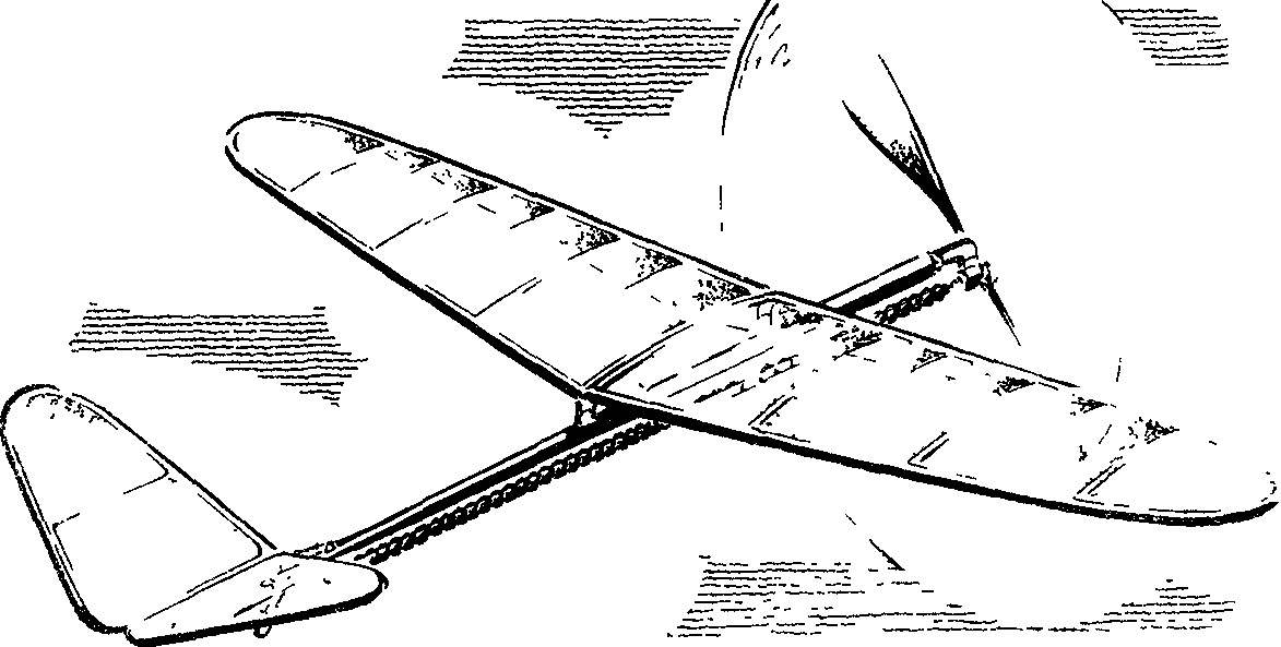
One of such attempts, we present to the court a model aircraft. Probably, in the design of this rezinomotornaya there are controversies. But do not rush to conclusions. The main thing – to understand that the class of schematic models has enormous prospects in terms of improvement in handling properties microapparatus, while maintaining the exaggerated simplicity of the technique.


We offer rezinomotornaya “pattern” has radically changed propeller engines. Single-vane propeller with the balancer is a counterweight made folding, despite sharply increased diameter. The point of this is to enable the model after the promotion of the rubber motor to hover for real, not having before him the air brakes in a stopped flow across the propeller. (By the way, even the freely rotating under the action of the incoming air screw has a resistance that is several times superior to the resistance of the model itself!). Important value of odnoapsidnymi with counterweight — ability when folded screw to maintain the alignment of even the lightest models.

Fig. 1. Schematic rezinomotornaya model.

Fig. 1. Schematic rezinomotornaya model.


The mechanism of the sleeve of the propeller provides automatic step change in the range of 8 degrees. This happens due to the suspension wire of the butt end of the blade in oblique (angle 45°) joint. The blade is drawn back rubber band. When the winding is necessary to provide a static torque equal to 0.02 kg*m. Then, at the beginning of the promotion, when the torque of the rubber motor is close to its maximum and a large thrust of the propeller, the blade moves into the cutting position relative to the sleeve, at the same time changing its installation angle. By reducing the torque of the blade gradually returns to its original position.


Fig. 2. Bushing of the propeller.

Fig. 2. Bushing of the propeller.


Talking about finishing the rotor group, it is necessary to note the lack of springs folding. The fact that in this scheme is enough dynamic pressure to the blade after the promotion of the harness securely went back. Pressing it to the fuselage is provided by a mismatch of the center of gravity of the screw with the axis of the suspension sleeve must be folded (when the screw is, of course, the balancing must be perfect). The rubber motor on the model made up of 20 filaments of a cross section of 1X2 mm. the screw Shaft rotates in two ball bearings.


The fuselage is represented by a carbon tube, although without sacrificing the weight and strength you can go to a simple rake or box structure made of wood. In the rear fuselage mounted hardpoints V-tail, which is clear from the drawings. The material parts of the node — D16T; stabilizatory surface are curved from a thin bamboo slats.


Fig. 3. The front part of the fuselage with the bearing hub.

Fig. 3. The front part of the fuselage with the bearing hub.

Fig. 4. Rear part of the fuselage with the knot of the whole control system.

Fig. 4. Rear part of the fuselage with the node of attachment of the stabilizer.


Wing design is a little different from the well-known options. Deserves attention system wing mounting on the fuselage, is able to facilitate the adjustment of the model when debugging. To do this, the tube of the fuselage are mounted two dural plates: back with a simple hole, and the front with an elongated vertically. The response plate, taped on the wing, simultaneously carries and struts for fixing the plane on the roll.


To improve profiling and increase the stiffness of the wing covered in the frame is additionally introduced nasal polonaruwa. Please note — centering on figures like size, counting from the edge of the wing and position the wing is not fixed along the length of the fuselage. The fact that the attachment points on the fuselage are placed only after complete Assembly and completing rezinomotornaya — then do not need to enter the balancing weights. The work on the tail section is important not only to facilitate the stabilizer (the weight on our model 3 g), and the suspension unit, the more that all its parts are metal. With careful implementation will be able to dramatically reduce the length of the bow, thus increasing the shoulder feathers.


V. SYCHEV, head of the society, Orenburg

Recommend to read

  • “ANT” OF SHOSTKA“ANT” OF SHOSTKA
    Isn't it interesting microntroller built young designers syut city Shostka in Sumy region? "It is easy and convenient to operate by the authors of the letter. The wheel we took from the...
  • AIR FERRYAIR FERRY
    Once in the journal "modelist-Konstruktor" I read the article "the Farmer's sloping field." The air route is very much needed in the highlands. But in nature, there are many horizontal...