SCHEMATICE WITH ICE…

SCHEMATICA WITH ICE...
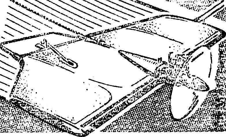
“School” model class F2D — further development of the schematic published in “M-K” № 7, 1986 in the article “Record holder… simplicity.” Indigenous improvements of the characteristics of the new device was able to achieve, preserve the unique simplicity of the power unit (which rivals and assigned to our bouzoukis the name “schematic”). This primarily refers to the stability of the start and the behavior of the model in the maneuver on the windward side of the flight hemisphere.

You’re already familiar with the option to satisfy almost all requirements and, moreover, greatly superior to the known design with the motor a working volume of 3.5 cm3. However, a small mass of bouzouki (made entirely of pine, it was lighter than balsa!) several complicated to run. Although in the hands of the athletes, more or less mastered the basics of aerobatics, the model has been out of competition, we decided to still do to improve it.


With the design agreed at once: the increase in mass is unacceptable — you will lose all the advantages in maneuverability. The solution was sverdiolas: just to deformirovanii shape of the wing. Warp “stabilizer” on the outer wing at the same time with the increase in the area last gave the model a sharp asymmetry in the resistance. In this way more than compensated resistance cords, and a betta never showed the desire to go in a circle. The tension was perfectly stable in all phases of the launch and flight.


In addition, the side installation of the rudder affected the distribution of lifting the vultures wingspan. Wherever you leave the wheel, it always works and at the same time as the flap, greatly reducing the load-bearing properties of the wing compartment. It is easy to understand that now the inner wing, despite the smaller area will always have a higher load-bearing properties. A further increase in the tension cords are secured.
Control line model airplane air combat under the engine working volume of 1.5 cm3.
Control line model airplane air combat under the engine working volume of 1.5 cm3:
1 — ending 2 — ending reinforcements, 3 — solitaire (pine, 3 mm thick), 4 — leading edge, 5 — spar, 6 — additional spar, 7 — area-rib pine (thickness of 1 mm), 8 — pad (plywood with a thickness of 1 mm), 9 — a covering (Mylar film), 10 — pad plating under thrust output, 11 — tabs strengthen joint edges (pine, 3 mm thick), 12 — Central rib (pine 6X13 mm) 13 — pull (solid duralumin wire Ø 2-3 mm), 14 — rocking, 15 — rib, the 16 trailing edge. The details of the poses. 1, 2, 4, 5, 6, 15, 16 are made of pine slats section 3X13 mm.
 
The scheme of the impact of the Elevator on the load-bearing properties of the adjacent wing.
Scheme of influence of the Elevator on the load-bearing properties adjacent compartment of the wing:
1 — raised helm position (corresponds to the input model in an explicit loop), 2 — flap position, required to increase load-bearing properties of the wing.
 
Compensation of the resistance of the cord.
Compensation resistance cord:
X PP is the resistance of the right hand console,
 
X L. p. is the resistance of the left console,
 
X R. the resistance force of the rudder,
 
X K. — the resistance force of the cord,
 
T — thrust power plant.
 
The impact of the inflection point of the thread tape on the maneuverability of the model when it is entered into the back loop.
The effect of the inflection point of the thread tape on the maneuverability of the model when input in the back loop:
A — model the classical scheme, B — the proposed model. L — shoulder to the point of inflection. For the same angle of attack the moment that prevents the rotation of the model, proportional to the value L.
 
X L. — the resistance force of the tape.
 
The forehead of the wing (variant).
The forehead of the wing (option):
1 — borders, 2 — forehead, 3 — spar 4 — additional spar.

 
Moreover, it changed the distribution of mass on the scale! Control mechanics are arranged so that there is no need to load the ending, in favor of matter and the transfer of the frame, and steering components of its suspension to the outside.
 
A careful examination of the new scheme revealed another important point. It turns out that the Elevator, in addition to performing basic functions, with a skewed axis of rotation works as a rudder. And always deflected in the direction required to maneuver.
Here you have a “small” change in the contour of the wing!
 
It remains to add that during the overflights revealed another advantage: superior maneuverability with tape on the reverse figures. Apparently, the game is now easier to drag the tail on turns — in fact significantly shortened the shoulder to the bend of the thread ribbon through the frame.
 
Structurally, the model is similar to a “prototype”. The only difference in the repetition power of the Central node on one of the ribs under the rocking control. For extra rigidity covered with film wing is increased thickness of profile: the frame is made from reek in the section 3X13 mm. other recommendations for the construction is completely analogous, see “Record holder… simplicity.”
 
Remained unchanged and the individual nodes. Only mount system helm was another. To “signal” from the pen of the pilot took place as accurately as possible, the axis of rotation is not located on the front edge of the rudder, as before, and 15-20 % of its chord. For this, apply the wire brackets from OVS Ø 1.8 mm. They primatyvajutsja to the trailing edge of the wing, and their bent ends are in and glued to the end rib rudder brass tube bearings. Other options are pendants. The important thing is to achieve the lowest mass tail of the model. If you are confident that it will succeed, we recommend that you extend the front edge of the wing. For example, to the cross section 3X25 3X20 mm or mm. This will allow you to move the engine back and down so the front alignment in the direction of increasing maneuverability. The benefits of such balancing is much more than the boot tail. Another solution is replacement pine front edge and corners-ribs bar foam PVC section 13X25 mm. Spar, of course, should remain to him and attached the foam. Helpful this brow before profiling to delineate pine rail 2X4 mm.
 
A. DARA, Moscow

Recommend to read

  • DIAMETER IN THE GRIPDIAMETER IN THE GRIP
    Sometimes the drills, especially in the already served, without distinction, the marking indicating the diameter. It would seem that to define it is only possible with a micrometer. But...
  • END-EXPRESSEND-EXPRESS
    For more convenient use of masking tape or duct tape, there are special tapes with a knife, not giving to the same after use to stick the remaining end. In the absence of such a device...