Workpiece screw (disc) turned from alloy D16T, brass or plastic. The diameter is selected depending on the diameter of the screw. The blank has a shank diameter of 25 mm, which is inserted into the spindle. At the other end there is a cylindrical ledge — the future hub of the screw. Accordingly, its diameter must be equal to the diameter of the hub.
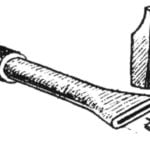
Mill — end standard. The diameter is selected depending on the screw pitch and number of visits. Due to the fact that the distance between the rotor blades changes depending on the diameter, the mill must grind pattern. To make a pattern with sufficient accuracy can be graphed. For this we need to plot the helical sweep surfaces.
On the vertical axis scale is the step of the screw N, while the horizontal circumference of the screw, starting from the outer diameter (ABOUT) and ending with the diameter of the hub (TH) with an interval of 5… 10 mm. Connecting the point a with all points on the horizontal axis, we obtain the schedule scan or spiral surfaces a graph of the angles of the blades in different diameters.
The pitch is divided ia the number of blades, in this case three cut. From points A1 and A2 lines are parallel to the lines AB, AV, AG, etc. the Distance between parallel lines is equal to the distance between the rotor blades, which can be determined more precisely by the formula:

The distance between the blades given without taking into account their thickness, therefore, the sizes it is necessary to reduce the thickness of the blade. For three-bladed propeller with a pitch of 48 mm cutter diameter equal to 14 mm.
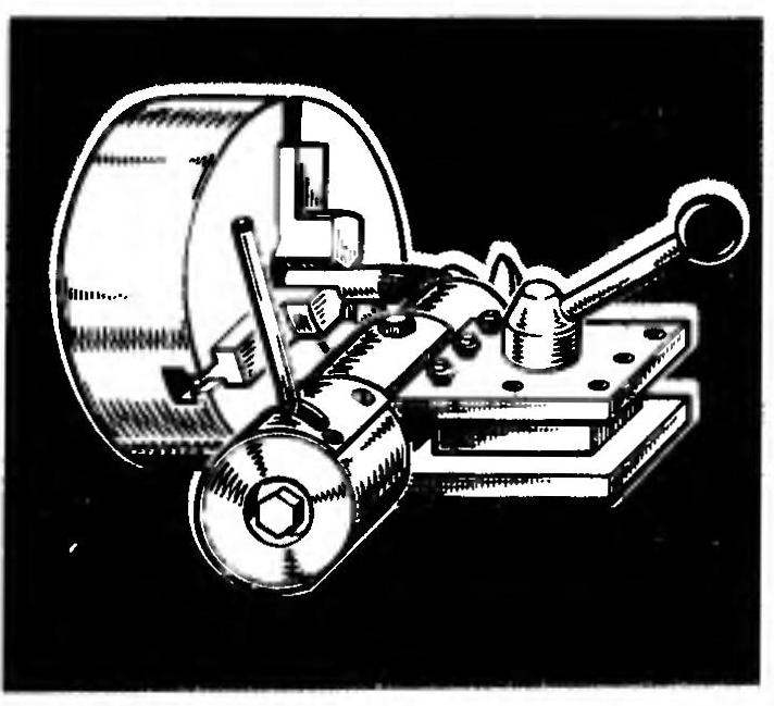
The order of work. For the manufacture of screw is needed to secure the fixture in the tool post of the machine, the cutter — cartridge; insert the screw blank into the spindle and tighten its bolts; using the handle to withdraw the spindle in the rearward position; handles longitudinal and cross feed of the machine to bring the blank to the cutter, as shown; turn on the machine (rpm — 60…7ОО); gently pressing the lever, start the cut grooves; and cutting through the groove to the end, to bring the arm to its original position, loosen the lock bolt to move the lever in the next hole of the spindle and repeat the operation of milling.
If, after slotting the thickness of the blades is greater than normal, the cutting should be repeated, achieving the desired thickness of the transverse feeding of the caliper of the machine.
In the manufacture of the “left” screws to begin cutting the slots you should be especially careful, because the cutter and blank are rotated towards each other, so that there may occur jamming.
After the grooves are cut and the workpiece acquired the form of a screw, must be inserted in the Chuck of the lathe and drilling the hole for the propeller shaft, and then cutting cutter “screw” cut into the screws.
A. KOLOTOVKIN, head of ship modeling circle, g. Klintsy, Bryansk.
Recommend to read
 SLIT WITH ONE BLOW
It would be good to have a set of different blades to the hose for irrigation, including end nozzle in the form of a slot: it has its advantages. And most importantly — this is easy to... AFRICAN “RHINOCEROS”
Developed industry of South Africa helped to create the country's advanced military industry, ranking in the global top ten by volume of its products. Enterprises of the state...