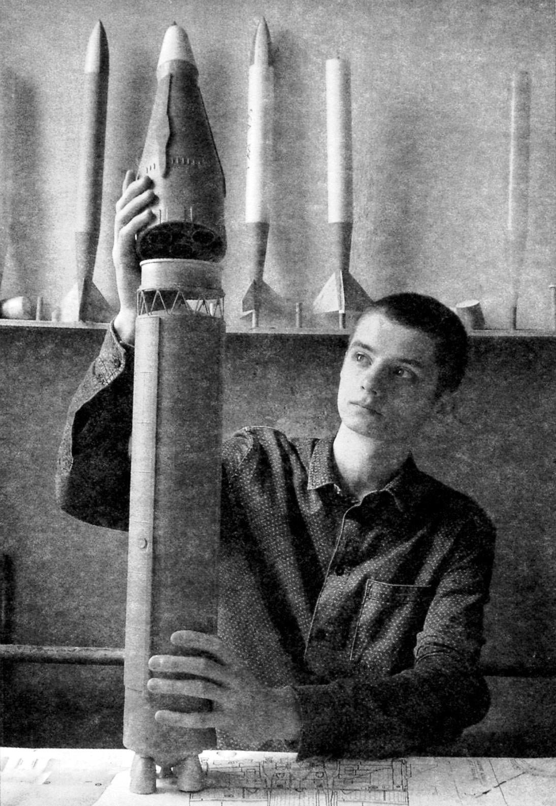
 With the proposal of developing a new Intercontinental ballistic missile operating on liquid oxygen and kerosene, and in 1958 was made by the Council of Chief designers. While its weight was not to exceed 100 tons, which is almost three times less than the starting mass of the rocket R-7 – the famous “seven”.
After all the studies at OKB-1, it was decided to design two options: the R-9A (index 8К75) and P-9B (index 8К76). During the preliminary design for R-9 the designers chose two-stage scheme with transverse division of the steps. The provision of TTX was achieved by adoption of a number of structural and layout decisions. It is the use of open truss cover for joint degrees; reset the tail section on the 2nd stage; the use of the vapor tank pressurization fuel 2-tier cut-off head part (MS) etc.
Product dimensions were chosen due to the possibility of transporting it assembled in a railway carriage and use of welding and stamping equipment, the R-7 rocket for the production of blocks of R-9. The required aerodynamic characteristics were achieved through the use of stabilizers and fairings for protection from exposure to air flow protruding nozzles of the engine on the 1st stage and aerodynamic flaps on the tail section of the 2nd stage.
R-9A is a two-stage rocket with transverse division of the steps. The first stage consists of an open lattice girders, the oxidizer tank, the instrument compartment, fuel tank and tail section. Steel transitional form of the welded construction serves for articulation of the steps between myself and the free passage of gases when the engine is started 2nd level. Tanks of the 1st stage load – bearing welded aluminum alloy. On the upper end of the oxidizer tank installed heat shield. Inside tank of fuel made the tunnel, which is the backbone of the oxidant.
In the tail section riveted construction installed four-chamber main rocket engine RD-111 developed by OKB-456 (V. P. Glushko) the suspension combustors. The rocket engine nozzle fairings mounted console of the stabilizer. Each of them consists of two parts: the pylon is rigidly connected with the housing, and the console. To transport the missile console was made removable.
The second stage consists of conical and cylindrical parts. The conical part of the housing consists of: adapter, fuel tank and oxidizer tank with miraculou shell. The cylindrical part is formed by the tail section, inside of which is placed boosters. Carrier fuel tank has a conical shape, and the oxidizer tank is the shape of a sphere. The propulsion system 2nd stage consists of a four-chamber rocket engine RD-0106 steering and RD-461.


Intercontinental ballistic missile R-9A (index 8К75)
The principal feature of the missile is included in the design of the adapter frame launch pad. The fact that the preparation for start-up required to connect to R-9 a large number of ground hydraulic, pneumatic and electrical communications. It was proposed to create a transition frame of the launch pad with the placement on it of the bulk of the nodes in the intersection of terrestrial systems with a rocket. Pre-start checks of the onboard systems practically was reduced to the pre-incorporation and regulation. All the operations were combined for the maximum time.
Flight test MRB R-9 was launched on 9 April 1961 and ended on military complexes in February 1964.
After testing ended 2 February 1964 54th start, the missile R-9A with mine and ground systems were put into service on 21 July 1965 under the symbol 8К75, and its mass production in 1963 transferred to the Samara factory “Progress”.
Model-a copy of the R-9A is made in the scale 1:27. The main material being used is paper and wood. Before you build a flying copy, you need to make two mandrels for casing: one length of 450 mm and a diameter of 98 mm, the other length 100 mm and diameter 96 mm. Mandrel is better to make metal, as for removing blanks (paper) they have to heat. But there is another option. Another mandrel (nozzle) should be carved from aluminum. Its shape is the ogive, the largest diameter 27.5 mm, length 39 mm.
Main body (1st level) is glued from two layers of construction paper with a thickness of 0.25 mm on the mandrel with a diameter of 98 mm. Size of paper blanks – 420×320 mm. the location of the fibers along the largest dimension. The workpiece is pre-moistened and wrapped once around the mandrel. The remainder is smeared with PVA glue and tightly wound on the first layer. After drying, the resulting workpiece is treated with a sandpaper (smooth out the seam) and paste another layer of paper “Delineator”, its thickness is 0.14 mm.
Having allowed to dry out paper, the workpiece is treated and coated with a layer of nitrocellulose lacquer.
Paper for removing the workpiece from the mandrel it first slightly heated, then placed in a cold Cabinet (in winter for the window). After 5-6 hours remove glued body and butt length 405 mm. This operation is best done on a lathe, after having clamped to the cartridge holder out of wood and making it the minimum speed is 50 – 70 Rev/min. at the same time you can make a razor-sharp pencil to mark Diametric welds on the body.
The same technology is made and two other paper details – the case of 2nd stage length of 76 mm and the caudal (motor) unit with a length of 63.5 mm and a diameter 97,4 mm.
At the top end of the housing 1 tier-glued clip, 35 mm wide, carved from basswood. It will be attached at the 2-level model by means of a sleeve with a transition farm. In the lower part of the main body, attach the tail block. And it then glued the tail cone, made of basswood and drilled four holes diametrically with a radius of 7 mm placed on diameter of 68.8 mm. In these holes are inserted the MRD containers and nozzles arched form. Their vyklevyvajut of paper on the mandrel by the method of papier-mache petals in five layers. Then treat the outside, butt length of 35 mm and is attached to the tail block. Outside of him hitting on four of the stabilizer. They are cut from glass fiber plastic with thickness of 4 mm and profile. The attachment of the stabilizers close curly fairings. Their vyklevyvajut in two layers of paper on a mandrel with a diameter of 64 mm.
The second stage-models includes a housing and fairing. The body is made by the same technology as the 1st stage. Its length is 94 mm. In the lower part of the insert bushing of lime and an inner diameter of 93 mm. it is attached the top element of the transition farm.


Model-a copy of the R-9A (index 8К75):
1 – nose cone; 2 – the lower part of the fairing; 3 – the case of the second stage; 4 – bushing; 5 – the outer elements of the model; 6 – transition farm; 7 – reflector; 8 – loop for the shock absorber; 9 – chute of the head part 10 – chute of the main body; 11 – wad; 12 – retaining grate; 13 – the case of the first stage; 14 – tail boom (motor) unit; 15 – the stabilizer; 16 – tail fairing; 17 – nozzle engine; 18 – MRD; 19 – nozzle command engine; 20 – fairing stabilizer
Fairing consists of two parts – the nose cone and the fairing. The nose cone carved from basswood, the diameter of workpiece – 100 mm. First make the internal conical bore (angle 9 degrees). For this, you need to make long – about 250 mm boring cutter. It can be done from a file on the grinding machine. Then, with a bore diameter of 90 mm and a length of 25 mm at the edge with a larger diameter, take out part of the cartridge.
Clamped it in a different frame, face piercing holes for diameter 90 mm and fix it to the nose cone. The connection would be superfluous to mark the dots of PVA glue. Outer treatment, butt length 157 mm. With narrow edge chiseled a hole up to a diameter of 43 mm. In it is inserted the cone. It is also carved from basswood in two steps. First, the workpiece on the machine chiseled from the inside under the cone 9 degrees. Then it is secured on the mandrel and processed form. Left side – the one that is closer to the cartridge – at a length of 15 mm is processed to a diameter of 42.8 mm, butt to length and covered with a nitrocellulose lacquer.
In case 2 tier-glued the nose cone and glue all outdoor items: hatches, piping and cabling wiring.
Transitional farm consists of three elements: the upper and lower bushings, the reflector and the farm. Top sleeve length of 34 mm is made from basswood on a lathe. Its inner diameter is 84 mm, the outer is 92 mm. On one edge made the rim diameter of 98 mm and a width of 2.5 mm. It is drilled on the circumference of the 12 holes with a diameter of 1.2 mm under the elements of the farm, that is under the pins. The lower bushing is also made of lime, its length is 14 mm, a landing the width of belt 10 mm, and a diameter of 96 mm. the Upper surface of the bushing is conical. The sleeve acts as a reflector gases when triggered, MRD 2nd stage. The farm itself consists of 12 welded corners, the ends of which are glued at the top and bottom of the sleeve.
The finished items models are assembled into one assembled all external elements – welds, rivets imitation, boxes, etc., and then coated with nitrocellulose lacquer. Guide rings (two of them) hollow out steel wire with a diameter of 1.2 mm and mounted on epoxy resin in a box at a distance of 380 mm. Color the model according to available copy of the photo. Primary color – ball (grey), fairing – white.
Flight weight of the model about 300 g. This option is made for a flight in one step with the use of four engines in the 10 N·s.
V. ROZHKOV


