Assembled model (with engine) must be weighed and balanced — after all, stable flight — the key to successful performances in competition.
One of the challenges in the design of sports models of missiles is ensuring their stabilization, i.e. steady flight at a given (vertical) trajectory.
It should be noted that one of the ways to ensure the stability of model rockets — aerodynamic — already included in their designs — installation of the stabilizers. But for the category “skyscrapers” will be useful to check, resistant or not, the aircraft is under the influence of external forces.
A necessary condition for aerodynamic stability is the mutual centre of gravity (C. t) and center of pressure (C. p. d) model.
If TS. located in front of T. TS. on, the model is stable. If TS. T. model behind TS. D., then — no. The ratio of the distance from the centre. so to TS. D. the length of the rocket determines the “stability margin”. For models with stabilizers it needs to be about 5 — 10%.
The center of gravity of the model (launch readiness) is determined by balancing on the edge of a school ruler.
To locate the center of pressure, you can use two ways: practical and calculated. For the first of any sheet material — plywood, cardboard, plastic, cut out the shape along the contour of a model rocket and find TS. so the very flat shape. It will be TS. D. models. But we have to admit that errors are inevitable. Practical insights you can confirm the second calculation method. For him drawing is a side view of the model and determine the area of each of its elements (fairing, hull, stabilizers, etc.). Note in figure C. so each element. The area of each of the geometric shapes which is determined from known geometrical formulas, multiplied by the distance from the top of the model to TS. so this element and get the resistance moment of a plane figure. The sum of the moments divided by the total area, will give the location of the geometric center of gravity of the contour or the center of pressure of the model. For this model missiles Э1В it will be equal to 215 mm. To change the position of the TS. so it is possible to download the head fairing.
“SKYSCRAPER” by A. KOZLOV
The originality of the two-stage model rocket S1B are connection steps through the MRD housing second stage and piercing the hull shape of the top step. The proposed method of connection of steps — almost jewelry work, requires certain skills. The shape of the housing of the second stage — piercing (with a variable cross section), and from the point of view of aerodynamics the solution is absolutely correct and competent. After all, the flight model for height happens mainly on the second stage (the first — to a height of 10 — 15 m). So the choice of the author on the shape of the case is perfectly justified. Now, specifically about the model.
The case of the first stage formed of two layers of fiberglass with a density of 20 g/m2, the mandrel shape with the largest diameter 40 mm and the lowest is 18.7 mm. After hardening of the resin the blank (with the mandrel) is clamped in the Chuck of the lathe and the outside is treated with emery paper of different grit. Then cover with two layers of yacht varnish “Parade L20” and cut along the lower length is 344 mm.
Inside the case glued: on top of the landing sleeve with an inner diameter of 10.2 mm and width 10 mm; bottom — five frames, four with an internal diameter of 4 mm and one bottom, its diameter is 10.2 mm. Inside the frames reinforce ognevoj — up of fiberglass with a length of 329 mm and a diameter of 4 mm. To lower his cut to a length of 9 mm glue Bush “landing” MRD of the first stage. It fits over the inner surface of the upper housing of the engine.
At a distance of 50 mm from the lower edge of the housing of the first stage to make it through (diametrically) the hole of 1 mm diameter passing through ognevoj. In this hole before the start of the thread for attaching the brake band (rescue system) first stage.
Stabilizers (or three) of the first stage are made of balsa plate 3 mm, profiles, reduce to the free edge to a thickness of 0.5 mm and the butt fastened to the body using epoxy resin. Then cover them with two layers of lacquer.
The housing of the second stage, as mentioned above, — piercing made in the same way as the case of the bottom step is formed on the mandrel of variable diameter: the largest — 18.9 mm and the lowest was 10.1 mm. After hardening of the resin the resulting workpiece is clamped in the lathe and at 270 — 300 rpm is treated with sandpaper and varnish. Giving it to dry, butt size (length — 134 mm without the head fairing).
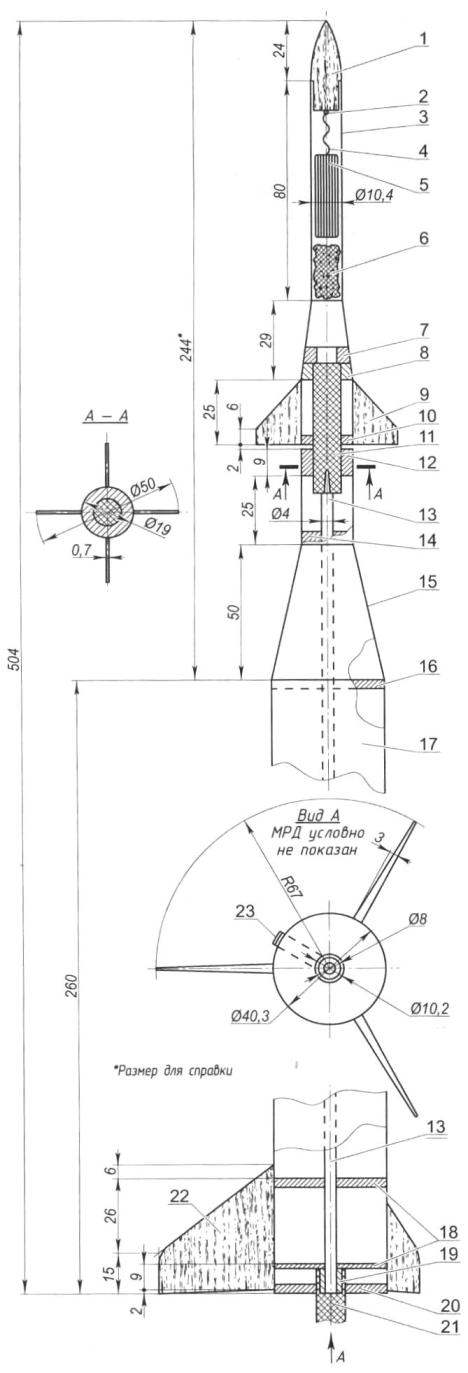
Fig. 2. A model rocket class S1B champion of Russia A. Kozlov (Ekaterinburg):
1 —fairing; 2 —loop suspension; 3—the case of the second stage; 4—thread suspension rescue system; 5—recovery system (brake band); 6—wad; 7—thrust bearing; 8 — centering bushing; 9—the stabilizer of the second stage; 10 — frame of the second stage; 11—MRD the second step; 12—bushing landing of the first stage; 13—ognevoj; 14—frame; 15 — transition cone; 16—ring; 17—the case of the first stage; 18—centering frames of the first stage; 19—Bush “landing” (binding) MRD; 20—the bottom frame; 21 —MRD first stage; 22 — stabilizer of the first stage; 23—recovery system the first stage
Inside the case in the lower (aft) part of the resistant and glued the centering sleeve and the frame, after making them in a hole with a diameter of 10.2 mm mrad. In the upper part of the body from the inside fix the halyard (the string of length about 800 mm) for connection with the head fairing, and mounting the brake band. Its length is not less than 3 m, the width — 25 — 30 mm.
The stabilizers of the second stage (there are four) are cut from the balsa plate with a thickness of 1 mm, the sides are reinforced with fiberglass, attach the butt to the rear of the hull.
Fairing — arched form, carved from basswood, and well treated with varnish. In the bottom (skirt) glued a loop for attaching the halyard.
Flight weight of the model without MRD and rescue system — about 20 grams. Kicks off “height” on the two engines “Delta” pulse of 2.5 NS MRD first stage of the retarder is not. His task is to give the model a starting “push” to accelerate to a certain speed. Its running time is not more than 1 — 1.2 s. the Time of operation of the retarder MRD the second step is chosen and practically is of the order of 6 — 6,5.
Training model for the start — it is responsible, requires skills and a certain sequence. Will tell about it in detail.
In this design (by way of connection steps) in the sequence of their preparation does not matter. For example, let’s start with the first (lower) stage. On the outside of the hull, in place of the diametrical holes, fasten the brake band is a strip of polyethylene foil size 25×300 mm, pre-folded “accordion”. Threaded through the hole presses a cotton thread and tied to the body of the brake band. Then in the frame insert of MRD and “plant” it on the sleeve (the connection must be tight, no backlash). Then from above we fall asleep in ognevo a little powder — one scoop (cut casings from a small caliber rifle with a length of 4 mm).
Next, stack the brake band in the housing of the second stage, pre-covered talc, cotton wool and paint (to create a colored cloud for better observation of the altitude of the disclosure of the rescue system). Then press-fit “set” MRD the second step, leaving it with a skirt length of 18 mm free. On it with little effort put on the body bushing of the first stage. The end of the engine thus rests on the upper edge of ognevaya. The distance between steps in the connection should not be more than 1.5 — 2 mm. To guarantee the nozzle of the engine of the second stage can sleep 5 — 6 grains of powder.
Takes off the gas dynamic model with the type “piston”, while the skirt is MRD first stage consists in the holder of this installation. After liftoff, at an altitude of 10 — 15 m lifting charge fires first stage engine. The firing pulse is transmitted by the tube-Ognevoy to the engine of the second stage, and she “goes” up. And at the same time there is the burning of the locking thread recovery system of the first stage, the brake band is revealed — and she lands.
V. ROZHKOV

 Category high-rise models (S1) is one of the oldest in the rocket modeling. Since 1985, the sixth world championship, it is firmly “registered” in all world and European Championships. It should be noted that our sportsmen became the leaders in it, and of the eleven world Championships last twenty years became seven-time Champions.