 Attempts to use the competitions to openly simplified educational technology in the classroom cord aerobatic models, naturally, can not give good results even when well developed the skills of the pilot. But, oddly enough, is equally deplorable results brings and following the design methods of adult artists. The explanation is simple: the boys, even a few years dedicated solely to piloting, may not be so rich operating experience of the championship-tion equipment and motors which are required when you use a specially designed professional “pilotage”. But the latter, as a rule, is, in fact, the epitome of achievement in this sport классе1 And any drawings of modern models-“Champions” (which become the base for the construction of even the Junior vehicles with engines of large cubic capacity) absolutely exclude any discounts on “ignorance” or “inability”.
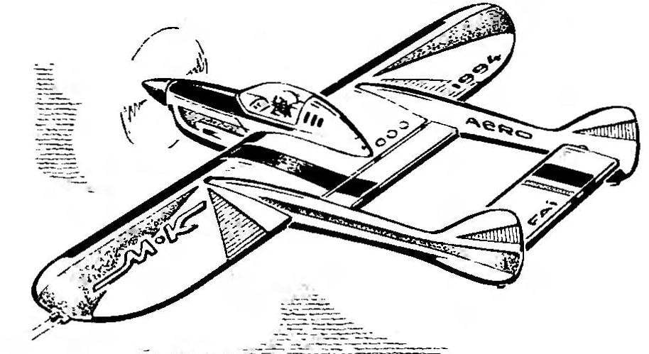
SUPERPOLITIK JUNIORS
One solution is to give juniors, who gained a certain experience in the pilot class, a special technique that has, so to speak, “intermediate” characteristics. A basic set of requirements — a sufficient degree of stability for increased maneuverability; ultra-reliable as the model and its behavior in the air, and (almost first) easy operation, reliable powerful engine.
One of the solutions to the problems we are about to submit today to the readers. Because the publication is not intended for novice modelers can not dwell on the intricacies of technology manufacturing pilotage — at the heart of its design is well known in the modeling techniques. But on what principles are laid down in the scheme offer machines, I think that would be helpful to know everything.
The main question is the optimal combination of stability and maneuverability. In this case, the requirements of the compromise satisfy both developed relative shoulder stabilizer with a relatively narrow wing and use of a control scheme with flaps. Immediately it should be noted that the all-moving tail — not a tribute to the race for super-maneuverability! Although among the many athletes there is a perception of increased efficiency of such a stabilizer and its associated signs of instability, in our case it is not.
