One of the first works of this team was the mobile missile complex 9К72. It included operational-tactical missiles R-17, and launcher 9П117 on a wheeled chassis of the Minsk automobile plant. The complex is intended for defeat important single, group and area targets at ranges of 50-300 km nuclear or conventional warheads.
The basis for the R-17 was tested and reliable R-11M, with the main constructive and geometrical parameters practically did not changed. In the upper part and installed a new instrument compartment with four large hatches to access the instrument flight control. The complex has successfully passed tests and in 1962 was adopted. Besides the Soviet Army, the complex consisted of the armies of the Eastern bloc, some Arab and some countries of South-East Asia, friendly to the Soviet Union. Rocket R-17 famous in the West under the code name NATO — Бсис1-V.
Rocket R-17 simple exterior forms and a good object for modeling in the study groups of rocket-space modeling of first-and second-year classes. It is perfect as a single-stage prototype for a competition in the class 85V model-copies on the altitude and can be used by novice copyists in the class B7 on realism of the flight. Model-a copy of the R-17 was developed in 1999/2000 in the laboratory rocket modeling of the Moscow city Palace of children (youth) creativity. For modeling the selected scale of 1:22 to the prototype. This was caused by using a production model rocket engine 5-3-6 mrad with a diameter of 13 mm and the existing technological equipment for models class Б5В.
The model design is also very simple and consists of a head portion 1, the casing 2 and a removable tail section 3 with the stabilizer. Moreover, the use of the latter greatly simplifies model preparation for launch. The head part consists of a cone 1.2 issued with its landing cylinder 1.4, 1.3 tube, centered in the upper end of the cone, and in the middle part of the frame 1.5, 1.1 tip and bottom of the frame 1.6. At the bottom of the tube glued to the umbilical cord of a parachute
1.7. The lower mounting ring with a bore cylinder provides centering of the head portion in the housing. Outside, there are elements of detailing.
In the lower part of the tube body 2.4 affixed to the landing the cylinder is 2.6, which is fixed to the engine compartment 2.7, centered frames 2.5. The outside of the casing located guide rings 2.1, elements of detail and Garg Rota 2.2, under one of which glued the umbilical cord of a parachute 2.3. Model rocket engine 2.8 engine Bay attached to a bamboo pin with the locking hook of steel wire with a diameter of 0.6 mm (for models of class B7).
The rear compartment is formed by a cylinder of 3.2, 3.3 mechanical frame, four consoles of the stabilizer 3.1, 3.5 feet gas 3.4 rudders and elements of detailing. It is fixed and scandinavan on
the mounting block cylinder and the cylindrical surface of the socket in the engine compartment.
The casing, the tail cylinder and motor compartments and the cone head portion is wound three layers of fiberglass with a density of 60-70 g/mg, impregnated with epoxy resin ED-20 and landing cylinders and tube head portion — of the four layers of fiberglass with a density of 25-30 g/m2. For winding the used metal mandrel coated with a separating layer of mastic “Edelvays” for polishing the floor. On the socket engine compartment is wound a strip of fiberglass to receive the cylindrical surface of the desired diameter.
After curing of the binder of the workpiece buildings shift and placed in a drying Cabinet for 2 hours at a temperature of 100-120 °C is the polymerization process. Without removing from the mandrel, the surface of the future of the outer hull, engine compartment and landing cylinders saw round needle files, then a lathe sandpaper (soaked in kerosene) first, medium, then fine grit, ensuring the smooth and sleek surface. Billet engine compartment cutter face piercing holes planting belt. Then, the blank is removed from the mandrels, preheated to 50-60 °C, and degreased with gasoline B-70. For blanks of the outer hull is applied with airbrush coats of epoxy primer. After curing, the blanks are put back on the mandrel and on the lathe sanded with fine sandpaper to obtain a flat and smooth surface. Then mark the items that are cut, removed from the mandrels and degreased.
Billet gargrota is formed of three layers of fiberglass (two density 25— 30 g/m2 and one 60-70 g/m2) impregnated with epoxy resin. For this purpose, a matrix and a punch, milled from Plexiglas or metal. They are coated with a separating layer, and the matrix still applied a layer of epoxy primer. First, the matrix of stacked thin, and then thick fiberglass, pressed them with a punch and assembled package is placed under the cargo or tightening the clamps. After polymerization of the resin to separate the matrix and the punch cut the workpiece gargotta.
The frames of the head portion and body are cut from the balsa plate of appropriate thickness, laminated with two sides thin fiberglass, and the frame tail section made of fiberglass with a thickness of 1 mm.
Console stabilizer molded into the matrix, consisting of two halves and cast in an epoxy compound for master model console. The master model is made from a pair of plates of Micarta thickness of 1.5 mm and plates foil-tion on both sides of fiberglass with a thickness of 0.5 mm. glued with First fix plate Micarta handle together to the desired size and give the desired profile. Then they are dismantled, is inserted between the fiberglass and glue them together. Then finally adjust the dimensions of the master model, polished surface and cause them to drawing and spot welding overlapping sheets of sheathing. In a piece of Plexiglas with dimensions of 80×40 mm and 3-4 mm thick, make a cutout exactly the size of the master model. Then the ends of the Plexiglas hang any thin plastic, creating a side: up and 15 mm down and 3 mm. from the Bottom insert in the recess of the master model and fixed the fix so that the middle of its thickness was located precisely on the top surface of the plexiglass with a large rim. If necessary, the gaps between the neckline and the master model is carefully filled with clay.
On collected in this way the mold is applied separation layer (dissolved in gasoline “Edelvays”) and a layer of epoxy primer. After curing the last mold is poured liquid epoxy compound (K-115, K-153). It is necessary to watch, that there were air bubbles. To remove them, it is desirable to evacuate the mold and shake on a shaker, which you can use any vibrating machine. After curing of the compound, dismantle the mold and remove the master model from the thus obtained halves of the matrix. Carefully control the working surface of the molds and, if everything is in order, it is the opposite slanting edges do vypily a round file with a diameter of 6-8 mm, one two, and another one required for a precise alignment of the halves of the matrix. In the finished mould is again placed on master model and repeat the process of preparing and pouring. After polymerization of the compound matrix apart into two halves and remove the master model.
Molded console as follows: on the cleaned surface of the matrix is applied consistently two layers separating and epoxy primer. After drying the latest on both halves of the matrix are placed two layers of thin and one thick fiberglass. Each of them impregnated with a brush the liquid epoxy resin. Then cut a piece of sintepon (synthetic wool) with thickness 3— 5 mm, exactly the size of the console, razrezajut it and invest in one of the halves of the matrix. Then apply the resin to all corners of the halves of the matrices, combine them and tightening the clamp. After curing of the binder carefully disassemble the halves of the matrix and remove the blank console, which remains just adjust the sizes.
Gas rudders, their base and the connector box is made from epoxy compound which in the forms that, in turn, cast out of silicone sealant under the relevant master models.
Model-a copy of operational-tactical missiles R-17:
1. Head part:
1.1 — headroom; 1.2 — cone; 1.3 — inner tube; 1.4 — MeV cylinder; 1.5 — upper frame; 1.6 — lower frame; 1.7 — parachute.
2. Body:
2.1 — guide ring; 2.2 — gargrot; 2.3 — parachute; 2.4 — housing; 2.5 — frame; 2.6 — MeV cylinder; 2.7 — engine compartment; 2.8 — motor MRD 5-3-6.
3. Tail section:
3.1 console stabilizer; 3.2 3.5 — start-up support
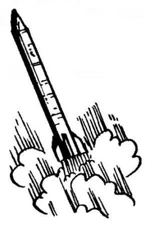
Operational-tactical missiles R-17
A drawing of the prototype was developed on the model of the missiles, on display at St. Petersburg Museum of missile troops and artillery
Fairings gargrota pushed out of annealed aluminum foil with a thickness of 0.1 mm by using a punch (cut from tough aluminum alloy) in the rubber. The tip of the bow machined on a lathe from hard plastic (Plexiglas, textolite or ebonite). Sweep riveted panels and hatches cut out of paper for Fax. Them to the front of Nakatomi the drawing is applied to spot welding, and with the inner ball of stylus pen squeeze “bolts” and “studs”. Then sweep paste into the appropriate places.
Before assembling the parts of the rocket all the scene changes degreased and sanded with coarse sandpaper. For Assembly using epoxy glue EAF with the preliminary clamping of parts drops tigrina. The Assembly begins with mounting the landing cylinders. Install the frames into the engine compartment, on the tube head part and in the end of the cylinder tail section. Their pre-fix, providing perpendicularity to the longitudinal axis of the compartments, and then splices shed glue. After its solidification compartments with frames inserted into the housing in the head compartment and glued.
Next, assemble the center pole. To the tube head part and the body of the model is glued halyards parachutes, skipping their respective cures lower frame tube and the hole in the housing at the location of one of Harrachov. The hole feature so that the tether does not interfere with the docking of the head part. As the umbilical cord using cotton thread No. 00 or flagellum made of monofilament SVM in six additions.
To cylinder tail section glued the console of the stabilizer and the base gas rudders, and body — simulated weld that is easier to carry from strips of adhesive tape. Next, assemble boxes of gargorov and their fairings. After that the joints spilling liquid epoxy glue, removing the excess. On the body paste the guide rings made from strips of fiberglass tube with an inner diameter of 3.5—4 mm and a wall thickness of 0.1—0.2 mm. On the end frame tail section mounted elements of detail to be painted in the main color.
Completely assembled parts of a model primed with silver on nitro or acrylic base to identify the roughness of the surfaces and crevices between elements of construction. Gaps sealed with putty (best for plastic models). After drying of primer and putty the joints and roughness of grind very fine sandpaper and degreased.
Model collection painted two or three layers of paint “, Nichego!” (you can use nitroemali) khaki (olive green, with satin surface structure). Each layer is dried at least 12 h, after which revealed irregularities sanded with fine emery paper. Then indicate the line of the supports and nanosat inscriptions. This is best done by the method of decalcomania, crafting decals, or paint through a stencil (you can use other ways). Elements detailing a different color separately painted by airbrush or brush and then mounted on the model.
On the halyards of the head compartment and the hull model-knotted loop, which through the rubber shock absorbers (double elastic with a diameter of 1 — 1.2 mm and a length of 150-200 mm) tie parachutes. Both of them have the diameter of the dome 500 mm (metalized lavsan with a thickness of 5-6 microns), and 16 ones. They differ in the diameter of the pole hole: for parachute body, and it was 10 mm, and for the parachute warhead — 200 mm. Before the first start, a model copy is fully assembled and determine the position of the center of gravity. It should be at a distance of 281 mm from the nozzle. If necessary, the tube head part of loaded clay.
To run the models use serial MRD 5-3-6 with a diameter of 13 mm, in which the delay time is reduced to 4 s In him falling asleep increased blew Noi charge of the four standards with a depth of
4 mm (from the casings small-caliber cartridge). Top lifting charge close the paper wad. The engine is mounted in the housing of the corresponding cover and fixed with a bamboo pin. Then establish into place the rear compartment.
Prepared two or wadding (cotton wool wrapped in a piece of cloth), one is pushed into the housing all the way down, poured a small amount of talc and inserted another. Fold the parachute of the body, wrapped it in the case of the Mylar film with thickness of 18-24 microns and placed into the case. Then just put the parachute of the head portion, place it on top of the parachute housing and install the head part. The engine is injected Elektrostal — model ready to run. Her starting weight 75-85 g.
The described procedure relates to the model-copy on the realism of the flight. For “tall” copies of it even more simple. Instead of two parachutes is one tape of a width of 30-35 mm and a length of 2-3 m of metallized polyester with a thickness of 12-18 µm. It is placed between the frames of the head portion and installing a single wad. In addition, in this class it is desirable to use a gas-dynamic start the installation of a “Cap” that will add extra height and allow to abandon the guide rings.
I wish you many successes!
Vladimir MINAKOV, honored coach of Russia,
the teacher of the Moscow city Palace of children (youth) creativity.
Recommend to read TWO CLOTHESPINS privernuty screws to a wooden cube, to help you quickly and accurately to solder the two conductors. SAUNA IN THE GARDEN During project development, and construction of baths, saunas in the garden, I proceeded from the fact that it took less materials and time. And this, I think I managed, mostly by... Scroll back to top

 (Model-a copy of the R-17). In October 1950, S. P. Korolev, the former at that time Chief designer of the Department of NII-88, involved in the ballistic long-range missiles, appealed to the government to develop a new missile to replace the obsolete P-1 was created, as you know, on the basis of the German V-2 (A-4). The proposal was supported, and in November 1951 a draft design was completed.The new missile was supposed to be more “simple and cheap to manufacture and easy to operate”. It was planned to use designed for anti-aircraft missiles V-300 liquid-propellant rocket engine operating on nitric acid and kerosene tractor with pressurization fuel supply system.