The frame is glued together from three pieces: two horseshoe-shaped plates and split ring. Plates cut from sheet glass, but with a third component is more complicated. It can be made from scrap plastic tube of appropriate diameter or baste 6-8 layers of tape IV fiberglass on a wooden disc and allow it to dry, and then cut the resulting ring.
Nichrome wire is wound on the frame with a small gap below the slider of the current collector does not knock on the coils. The ends of the winding soldered and tin the petals placed under the heads of the two screws M2, attracting the coil to a fiberglass Board. Moreover, between the charge and the coil should be a gap. It’s enough to put washers or screwed on the bolts at the nut, otherwise the winding will overheat and the fiberglass will start to smoke. Runner here — the finished part is taken from the variable resistance type SP-11.
The coil of the rheostat is connected to the housing of the steering machine of the dural area. All connections are done with a short two-millimeter screws.
In the center of the coil axis, the bolt M4, which is from the bottom up sequentially planted: as fast or as slow Bush (she ruskamen in the circuit Board), a collector, a slider, movable bushing, gear and nut. Last worn cover made of polystyrene, it keeps the axle in a vertical position.
Speed control screw:
1 — steering machine, 2 — area, 3 — bolt, 4 — wire rheostat, 5 — tab, 6 — frame of the rheostat, 7 — runner of a current collector, 8 — cover, 9 — the guide. 10 — front cover, 11 — comb, 12 — wire feeding machines, 13 — nut 14 — gear, 15 — movable sleeve, 16 — collector, 17, the fixed sleeve.
Now more about those details. The fixed bushing is intended for mounting of the current collector. Fixed he flowed to his “language” was directed toward the slit in the housing of the rheostat. As the current collector made of foil fiberglass, the foil on the “language” of soldered wire, which, together with the two wires from the coil of the rheostat is the harness that feeds the motors. Strictly speaking, in the electric circuit except the power source, motors and controller is described must be present another element — the reverse switch, but the conversation about it will go in the future.
The current collector foil of one of the contacts slides the slider (the other contact on the coil]. A slider with a movable sleeve connected with core — raskere. Bushing on the axis of the fixed cylinder and screw. By the way, raising or lowering the movable sleeve, it is possible to regulate the force with which the slider is pressed against the winding of the rheostat.
Further gear. Moving to the Bush she pressed on top of the nut and serves to convert the reciprocating motion of the dies in a rotary movement of the runner of a current collector. The plastic gear has 16 teeth. She is carved out of a dual pinion steering from the faulty serial machines, its axial bore enlarged to Ø 4 mm. of Course, you can apply and other appropriate gear, including metal. Importantly, the step of the teeth matched the combs.
Combs used cars from the steering equipment “Suponer”. They are cropped and pinned to the gear rails made of polystyrene that are glued to the cover. She, in turn, screwed to the rack attached to the body of the steering machine.
A few words about the adjustment of the unit. Assembled the regulator must provide the following voltages: 9V, when the slider of the current collector is in the beginning of the rheostat coil, that strain of the forced mode of the engine (takeoff elektroleta, climb, turn), 6V — runner in the middle of the coil (steady flight) and 3B — at the end of the coil (pick up and “small gas”). Selecting the number of turns, it is necessary to achieve such voltage values. Then the corresponding thrust propellers will inform the elektroleta speed required for these modes popeta.
Power motors from a separate battery STS is 1.5. Steering the machine of the speed controller powered by a battery tsnk-0,45 — source receiver power supply and all equipment. It is located in the fuselage, among other radio control device.
S. PODGURSKY
Recommend to read
 TESTED IN THE SKIES OF SPAIN
High-speed scout-bomber-70 BLITZ. One of the most famous planes created by the German firm Heinkel (Ernst Heinkel Flugzeugwerke GmbH) in the early 30-ies of the last century, became a...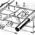 PLANE FOR TWO
Since the days when "Tsar Peter arapa married", carpentry work associated with a large number of planing boards or timber, produced a two-handed plane. Such a tool would no doubt be...

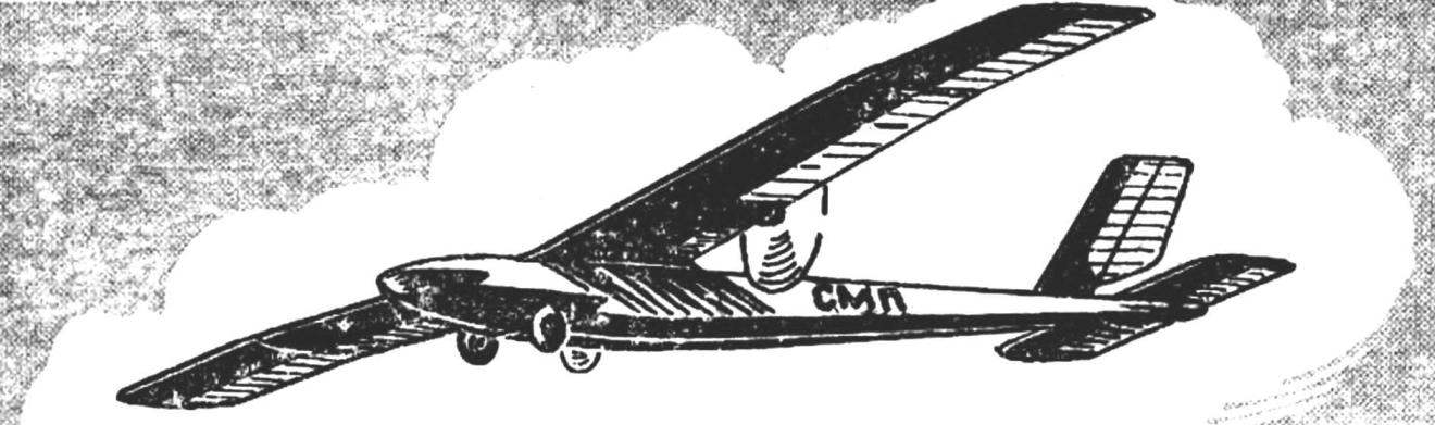 In the past year (“M-K” No. 5 of 1979), we introduced our readers to the technology of refinement of microelectromechanical DI-1-3 and EDR-40 to install them on a flying model. The article evoked a wide response among modelers. Yes, otherwise it could not be: after all, nowadays, no one not vysavac>1 doubt the prospects of application of electric motors not just for cord, but for radio controlled models free flight. However, even the best examples of electric motors are still unable to compete with internal combustion engines primarily by power density, its weight IS1 resident students nutrition.