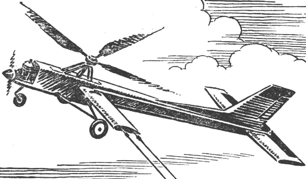
Model autogyro designed and built in the laboratory of the Aero modeling club of young technicians of the Siberian branch of the USSR. The author is a graduate of the class of technical physics and mathematics school Ilya Skiba. The model is made in Cordova. In this case adjusting it is easier than Svobodnaya. The design of the autogyro is quite simple. The fuselage, landing gear, empennage, engine mountings — as a conventional cord models. A three-bladed propeller creates lift, rotating from the incoming air flow, that is, using the phenomenon of autorotation. However, the number of blades may be three, four or more.
The fuselage (Fig. 1) stacked design, assembled from plywood formers and pine stringers. The basis of the bow is the most simplified engine mount of beech. The front fuselage of rectangular cross-section in the tail — hex. Nasal frames from plywood thickness of 2.5 mm, the rest 1 to 1.5 mm From the sides of the bow section sewn plywood with a thickness of 1 mm at the transition of rectangular cross section in the hexagon fairings made from foam. At the top of the fuselage on the epoxy glued two guides from dural area cross section of 10X10 mm, which installs bracket of the mount of the rotor.
Tail inlaid design, the ribs of the fake veneer of 1 mm thickness, edges and spars of pine. The profile of the stabilizer is symmetric, it otnositelnoi thickness 9%. The rudder is deployed to the right by 15°.
Chassis tricycle, with a nose wheel. Front wire OVS Ø 3 mm, rear Ø 2,5 mm struts Ø 1,5 mm.
On the left side of the model are attached to a small wing in which there is a dural rocking with a thickness of 1 mm and a thrust for attaching a cord from a steel cable Ø 1 mm (Fig. 2). The axis of rotation of the swing 10 to 15 mm behind the center of gravity of the model. Wing of duralumin D16T with a thickness of 0.5 mm is glued into the fuselage is epoxy resin.
 Model autogyro designed and built in the laboratory of the Aero modeling club of young technicians of the Siberian branch of the USSR. The author is a graduate of the class of technical physics and mathematics school Ilya Skiba. The model is made in Cordova. In this case adjusting it is easier than Svobodnaya. The design of the autogyro is quite simple. The fuselage, landing gear, empennage, engine mountings — as a conventional cord models. A three-bladed propeller creates lift, rotating from the incoming air flow, that is, using the phenomenon of autorotation. However, the number of blades may be three, four or more.