 Racing airboat motor. In the journal “modelist-Konstruktor” is not just talked about RC racing boat with aerodiesel. In contrast to the models with the propeller for gliders with a propeller does not require complicated gear reducer and transmission: because the propeller is mounted directly on the motor shaft. And the engine for the model”train” to get much simpler: in any auto shop, you can buy a suitable 12-volt electric motor, for example, the one that rotates the windshield washer pump or used to Windows. It facilitates the work of the Modeler and allows without difficulty to produce an airboat even the novice athlete.
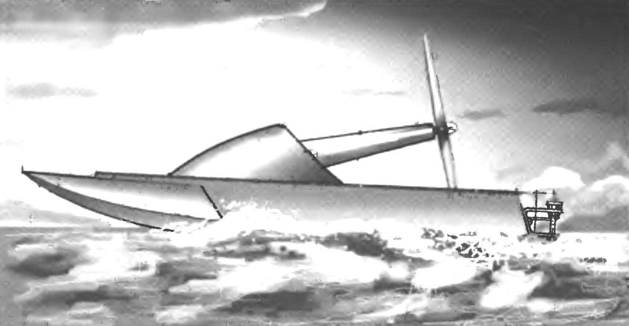
In our today’s post tells exactly about this RC racing boat — with the engine from the “Zhiguli” of the pump drive washer.
When designing aerolister it should be borne in mind that its driving characteristics will affect not only the contours of the body and aerodynamics of the model. To obtain the maximum thrust of the screw is necessary to properly direct the flow of air as in front of the propeller and behind him. The contours of the front of aerolizer should not cause the failure of the incoming air flow, and back — not to “lock” it: it can significantly reduce the thrust of the screw and thus the speed of the model.
The use of the washer pump allows to solve the problem associated with the location of the power plant on the glider: thanks to the elongated shaft of the motor will be able to significantly lower the center of gravity of the craft. For example, as shown on the drawings.
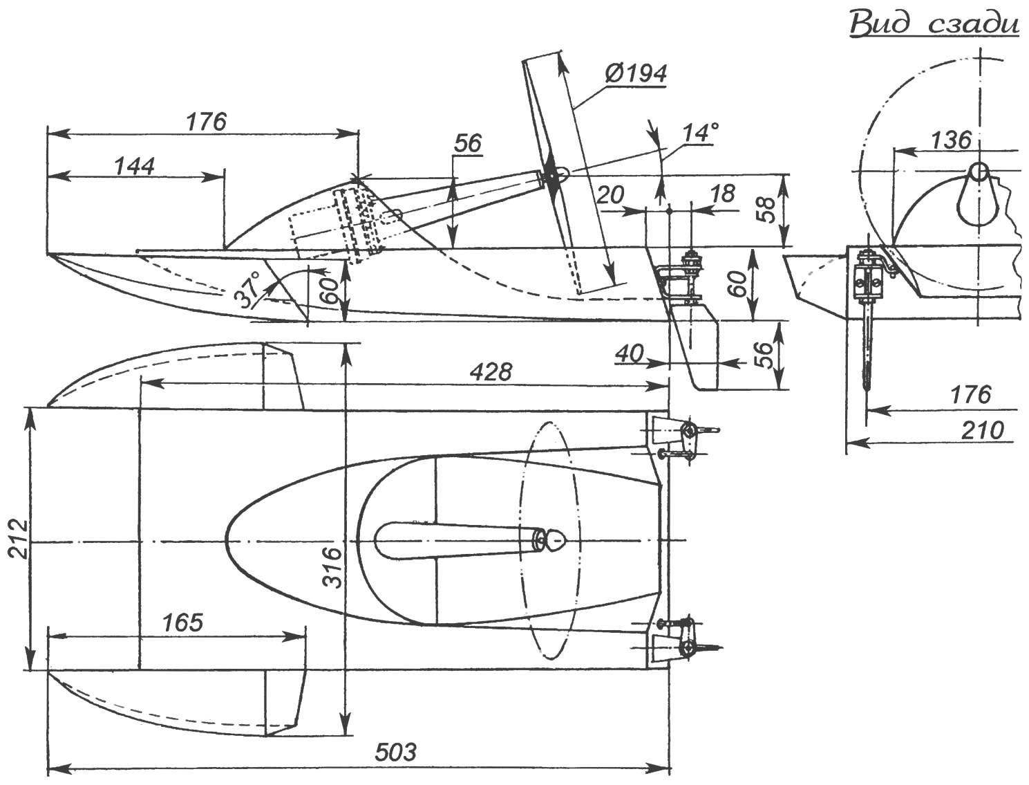
Geometry racing model aerolaser
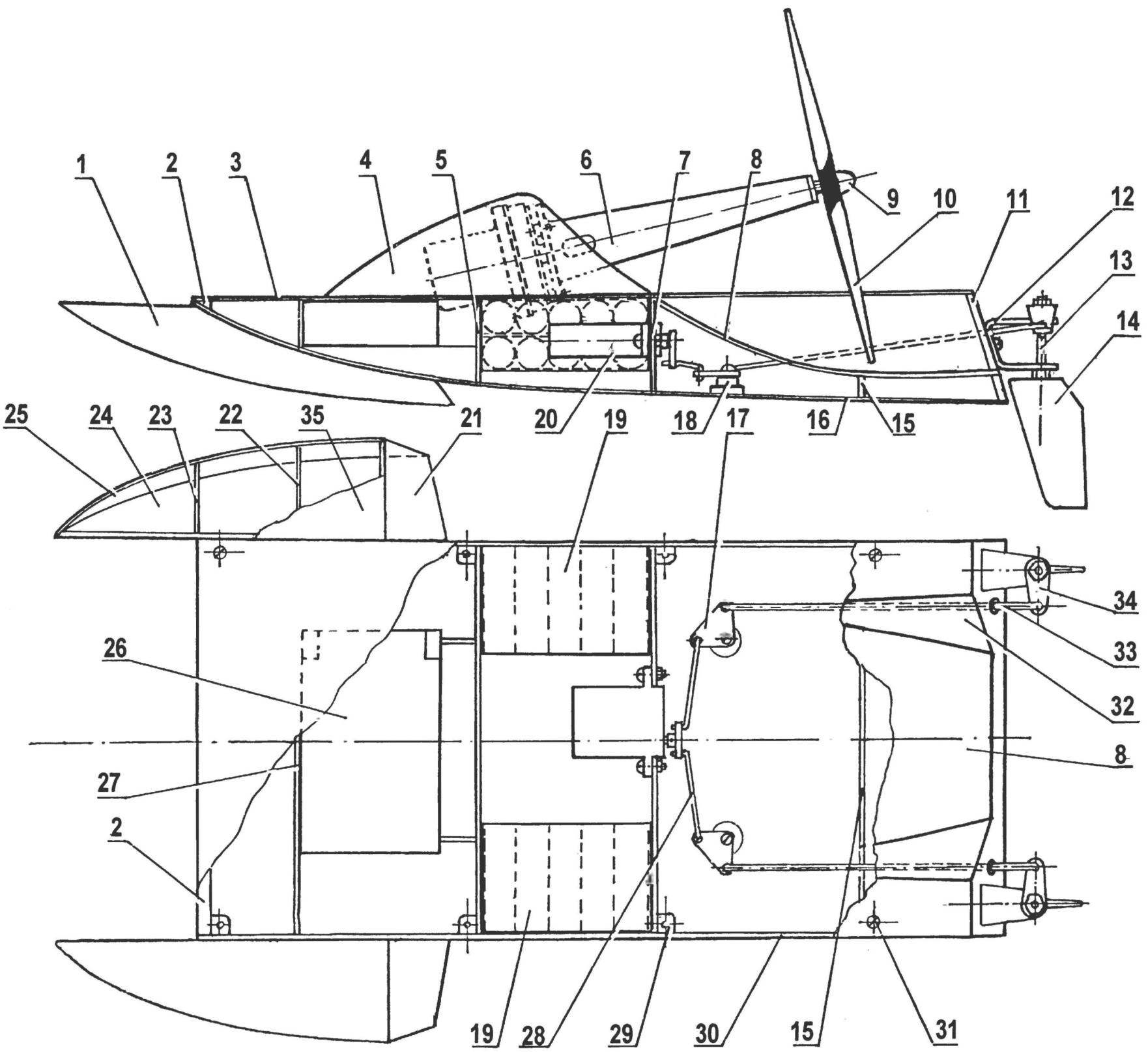
The layout of aerolister:
1 — internal forces and the lateral wall of the float (plywood s3); 2 — cross (pine, rail 10×15), 3 — deck plating (plywood s3); 4 — fairing (Vileika of fiberglass and epoxy resin; 5,7,15,27 — frames of the hull (Linden, plate s5); 6 — power unit (electric car washer); 8,32 — rear of the deck (plywood s1); 9 — propeller spinner; 10 — propeller Ø194; 11 — transom Board (Linden, plate s5); 12 — bracket of the steering device (aluminum, sheet s3); 13 — steering shaft (steel, stud M4); 14 — steering pen (plywood s4); 16 — the bottom (plywood s1); 17 — steering l-shaped lever (aluminum, sheet s3); 18 — an arm of the steering lever; 19 — battery; 20 — steering car; 21 —transom Board lateral float (plywood s3); 22,23 — frames and lateral float (plywood s3); 24 — bottom side of the float (plywood s1); 25 — Board lateral float (plywood s1); 26 receiver remote control equipment; 28 — the transverse thrust steering (steel knitting needle Ø2); 29 — anchor nut (PCB); 30 — power panel (plywood s4); 31 — a screw M3 mounting deck; 33 — longitudinal traction steering (steel knitting needle Ø2); 34 — oneplace steering lever (aluminum s2): 35 — deck side of the float (plywood s1)
Manufacturer aurolectroless best to start with the hull. His frame going from the front crossmember (rack pine), a pair of sidewalls, four frames and transom planks (lime plate thickness of 5 mm) and is sheathed with plywood with a thickness of 1 mm. In frames it is necessary to provide openings, scuppers, and in the back is another sealed plastic tube: when injected into the body of water it will be easy to remove. To ensure water resistance, the case inside should be covered with two or three coats of varnish parquet.
Deck of 1-mm plywood, removable, which provides access to receiver, batteries, steering machine and the steering mechanism. To the body of the deck screw with a spherical head. Fairing of the engine — vikla-ka on gypsum disc from fiberglass and epoxy resin.
The frame of each of the side floats consists of a wall, transom boards and two frames (plywood thickness of 3 mm). Deck plating, bottom and sides — plywood with a thickness of 1 mm. assembled with epoxy glue. In the frames of the floats should also be a couple of holes of scuppers and transom Board hole with a cork plug. Inside the floats would be a good idea to cover two or three coats of varnish parquet.
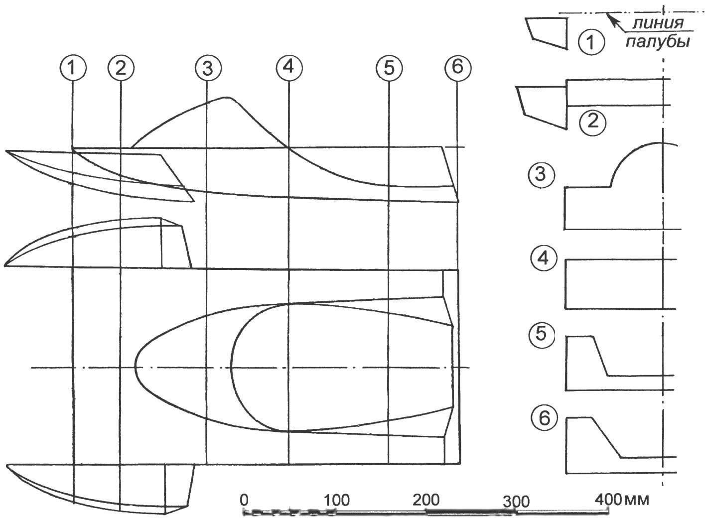
The theoretical drawing of the hull of aerolister
The docking of the side floats and the hull is made by a pair of screws with nuts, the latter are fixed from the inside, to force the walls of the floats with epoxy putty. At the stage of debugging aerolizer necessary to fix each of the floats only one screw, and only after determining the angle of their installation relative to the housing in the process of trials is to strengthen finally.
Steering device — dvuhmetrovoe, consists of a pair of dural tail brackets and two feathers, carved from beech plate thickness of 4 mm. Tail feathers are controlled by longitudinal rods, which with the help of the l-shaped levers duplica transverse rods connected with the steering machine.
I. TEREKHOV
Recommend to read
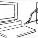 THE COMPUTER ON THE CIRCUIT
As you know, power outages often lead to loss of information entered in the RAM of the personal computer. And nine times out of ten this trouble occurs in case of accidental pulling of... ROLLING WARDROBE
Large sibelectroterm plants from time to time organize specialized exhibitions, where to study avenues its primary products are making their drawings. Among other things come across the...
