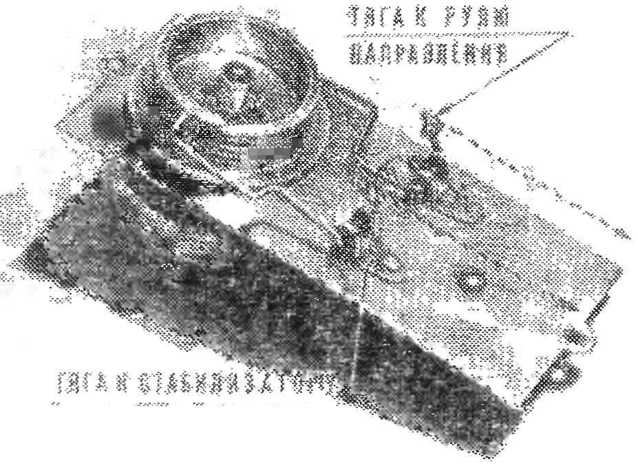
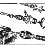
 This timer deflects the rudder in 45 with since the start and after 2 minutes of flight puts the model in the parachuting mode deflection of the stabilizer at 45°. For its production used the mechanism of the self-timer the camera “Kiev”. Alteration is simple and can be done in the aeromodelling laboratory with a lathe.
Self-timer the camera apart, removing all the leverage and strength spring, easy circuits 6 and 11, leaving around 2— 3 mm holes for the installation of gears. In the circuit Board 6 drill another hole and cut it-thread M1,4 for mounting the housing under the spring. With fee 11 should not remove the gear, as it is connected to the node of attachment of the rocking chair, holding the ratchet wheel shaft from turning. This cut Board bracket power springs and drilled two additional holes to set the self-timer on the Board 13. For this purpose, the cracker 10 tapped No. 1,4.
Spring is better to take a CD from the dial pad of the phone, cutting off one third of its length (33 cm). Body and cap machined from duralumin D16T. In the bottom panel drill three holes Ø 1,5 mm for mounting it on the Board, and on the wall make propyl for fixing the end of the spring. The inner end is held on the shaft with the retaining clip and pins. Retainer-Cam need to facilitate cut down lower part of it.
At the end of the shaft from the installation of a latch-eccentric drilled hole Ø 1.3 mm at a depth of 3 mm and cut a thread M1,6 for fastening the housing cover the springs with screws and washers.


Fig. 1. Timer device rezinomotornaya models:
1 — washer 2 — housing cover 3 — housing 4 — spring retainer 5 — pin, 6, 11, 13 — Board, 7 — gear, 8 — anchor, 9 — spacer, 10 — cracker, a 12 shaft, 14 — disc mechanism for the rudder, 15 — reel, 16 — spring 17 — bracket 18 — lever, 19 — rivet, 20 — bushing.
The drum is made in the form of a worm wheel, the same as the disk has six holes that allow you to change time deflection of the rudder and stabilizer in a wide range with sufficient accuracy. The disc is a slot to release the lever, the associated thrust with the rudder. The second lever made of wire OVS Ø 0.8 mm connected with a stabilizer. One end of it flat for sliding in the spiral groove of the drum, the other soldered to a washer, preventing falls loop thrust. The length of the lever select position. Dural bracket secured to the circuit Board of the timer by two rivets. Lever transmitting commands to the rudder, is provided with a spring steel wire Ø 0.3 mm, prevents the return of the lever to its original position and into the slot of the disk in order to avoid stopping the timer.
Board 13 from dural plate thickness of 0.5 mm, has two holes for mounting to the pylon of the model. It above the pendulum drill hole Ø 0,5 mm in which is inserted the pin. It prevents the swing of the pendulum in the cocked position of the timer and releases it at the start when pulling.
After Assembly the mechanism should be washed in gasoline to remove metal particles. Washed and oiled the timer makes one rotation in 50-55 C, its weight is 12 g.


