Hand on heart it is necessary to recognize that new developments do not stand up to scrutiny on any of the items. The aerobatic properties of all three are incorporated into the scheme as poor. And indeed if they talk, if wing loading “pilotage and bouzouki” almost 50 g/DM2 , and the difference of mass of the engine and extremely heavy tail section these models do not have analogues? Yes, such a device with well working engine will still be able to make hinges. But only in the runes of an experienced athlete, and then only with difficulty, and the beginners even do not have to think. And where can I get good running engines?
So, it is only a training model? But this assumption is not tenable. The strength cord “coaches” as if deliberately laid miserable when still quite time-consuming in execution of the design. Openwork frame of the wings are greatly alleviated ribs from mm plywood and the main load bearing elements of the rails having a given rough surface section is not more than 3X3 mm. It is not bonds and paper skin, which plus after the completion of all work covered by nitrocellulose lacquer in two or three layers in accordance with the instructions. But the use of any nitro lacquer offered for sale in hardware stores, not only provides the necessary sail tension, but also gives her the extreme fragility! As a result, the wing “fray” even with careful planting or already in the operations to start the engine. Maybe the fuselage meets the requirements of at least the training model? However, although at first glance it seems disproportionately periodiocally, in fact, severely weakened by the recess Windows of relief. The latter gives the gain in weight of about 50 g (at 0.5 kg!), multiple loss of strength compared to one piece even more delicate and sensitive increase of the labor intensity… Add to the above mention of the fuel tank, which volume is not enough and a third AFCS or the time of the battle; no zalivok of the spar at the root and the wing tips; application obscure “torsion” of the lever connection of the halves of the rudder, which in combination with a completely non-rigid compression rod “provides” an unpredictable behavior of the model in the air and you will get a sufficient idea of the new set. Note that we have not thought about the concept of the proposed young athletes “modern” flight and fighting machines! And about the speed options you can talk only using quotes.
However, criticism of the criticism, but in any case it is meaningless, if not constructive. What do we offer? No, not to eliminate the production of the only sets of assumptions. All you need is… differently are embedded in them blanks! About how to do this, our story today.
In the processing of the original scheme focused on the improvement of flying properties of the model by reducing wing loading and reducing the moment of inertia about the rotation axis in space. In parallel, it was required to simplify the design and improve strength in General.
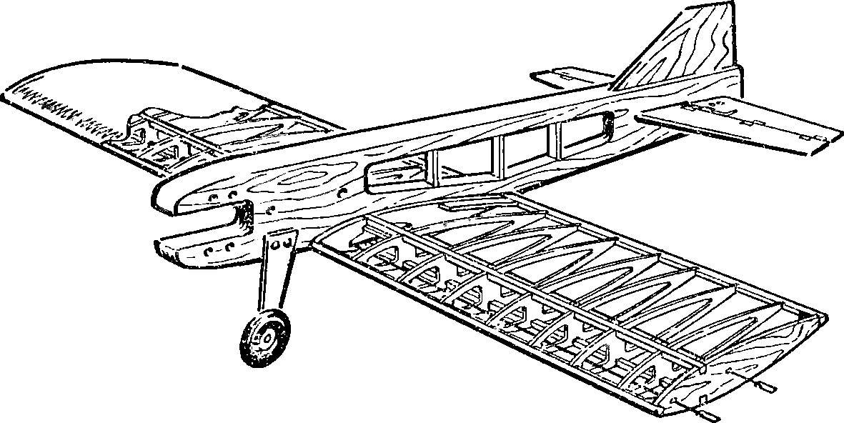
Reflections on the design of the wing led to the decision to abandon 14 weak lightweight plywood ribs in favor of… four powerful, cut no window of relief from the same material. Even more good strength results are obtained using an ordinary wooden ruler. Between the ribs are mounted “spouts”, whose main goal is not so much in the maintenance of skin, how much of the spar. The latter is executed from the original pieces, only across the span of the split is pasted a wall of mm plywood. The trailing edge of the original, and on the front there are two strips, carefully cut from the longitudinal edge of the blank of the fuselage. After calibration using a plane they must have the same cross-section as the trailing edge.
The principal dimensions of the original model (A), its first modification (B) and second modification (B). All images are made in the same scale.
An unusual connection of the halves of the elevators on the first modification of the pilot.
The markup is regular harvesting of the fuselage for longitudinal sawing.
The fuselage of the second modification of the model.
Fuel tank (put a coil of yarn along the axis of the model, when assembling the wing to glue between the plywood sheathing of the wing).
The fuselage vystragivaetsja of the regular blanks, but now has a cross-section of 15Х65, but only 10X40 mm. as a result, new one-piece billet lighter original lightweight one and a half times! The tail part otrygivaetsja to a thickness of about 4 mm, and the sub with both sides glued with plywood, and mounted at the same time the influx and lower the bow for easy placement of the screw holes mounting the engine to the narrow fuselage and one of the seats of the fixing chassis aerobatic version of the model. Keel weight savings from the tail of the device is greatly reduced in size, and the game is not at all like an imitation of the cab.
The horizontal tail is left unchanged, because the reduced mass is already achieved by the elimination of extreme preteenie the rear of the fuselage. Originally performed by the connection node halves of the elevators — using short staples and two fabric strips. Fighting is the best option to build with a shortened fuselage and uncut wheel.
Fuel tank have to cut out of tinplate again. It needs to have a volume of about 50 cm3 , according to the scheme closer to the original. Alignment is a fully equipped model is 40 mm from the leading edge of the wing, close-fitting Mylar on glue BF-2. Flight characteristics much higher than the initial version of the model, and snakes can be considered quite satisfactory. About the strength you can judge for yourself by comparing the pictures.
Wing:
1 — the leading edge-spar (pine 15X16 mm, docked on the “condition” of the two halves in the middle of the scale on a plasticized epoxy resin. The length of the “whisker” not less than 100 mm), 2, 4 — scarves (plywood 3 mm), 3 — intermediate rib (lime 2.5 mm), 5 — a lining of the center (1 mm plywood), 6 — fuel tank 7 — regular the gym, 8 — Central falcinellus (use the cut fuselage, formed after cutting out the window under the wing), 9 — a scarf joint edges (plywood or pine 3 mm), 10 — trailing edge (full of set) 11 — tail of the gusset plate (plywood 1 mm), 12 — eyeliner rocking, 13 — wires from the camera (the Central core element), 14 — ending, 15 — washer (plastic) 16 — stand (plywood 3 mm); And — staff pattern of the workpiece ribs.
All-moving stabilizer (the entire frame and pine slats from a set of cross-section of 4X4 mm, calibrated up to 2,5X2,5 mm).
The stationary element of the horizontal tail and the wire edge of the keel.
Scheme of the Assembly of the stabilizer and the mounting of additional elements.
The second modification
Despite significant improvements in all of the characteristics of the set and the models, work on finding optimal solutions has continued, and the result was fortunate on the basis of the original blanks to construct a new, very interesting car. A considerable advantage provided by a number of publications in the “M-K”, which provided an extremely simple and effective scheme of the wing cord.
I think that the special explanations of the second modification is not required, and on the design merits it, you can judge by the photos.
This can be a model, assembled from parts of an ordinary set.. It is only necessary… to properly use blanks!
In the pictures, except the common kind of aerobatic model aircraft, is shown: drive unit rotary stabilizer, the nose of the fuselage with a modified engine MARZ-2.5, and removable landing gear (next — regular wheel).
The rudder is plywood as end plate of the stabilizer. Plating of metalized film.
As one of the initial billet of the fuselage to just three main power details, it is clear from the drawing. It is important to use a good fine saw, so that after planing the newly acquired billets to meet the required dimensions. Adjustment of the thickness of the fuselage is carried out after the filing of the workpiece along the contour marking — the cropping used for the other parts. Imitation canopy and fin on a flight option made from aluminum knitting needles 2,5 mm. Ø the ends are degreased, tightly wrap a thin thread and glued into corresponding slots in the fuselage. On the finished plane model delayed Mylar film. The rear part of the contour of the keel plate at the same time protects the fuselage from cracking and increases the reliability of the joint parts.
Special discussion deserves the original design of the stabilizer. He was going to made a life-size drawing, a tightened film; and first, without the lower beam flange. After curing, epoxy adhesive stabilizer is removed from “the pile” and debrugheta the other elements. Despite the apparent subtilest, with careful gluing of the frame and well done with the cording he “experiences” more than one model! Hog cut out of strips of aluminium, the hinges of the hinge can be of any design — just to provide minimal backlash and smooth running of the “wheel”. Two-gear mounted on the fuselage or wing.
Alignment of the device is the same as in the first embodiment. After acquiring the basic skills of piloting you through the installation of an engine, Coca and the propeller to shift the center of gravity back another 8-10 mm. Loading of the tail highly undesirable! Under the new balancing as flight and fighting to remain highly sustainable “in the horizon”, but the flight characteristics reminiscent of a good balsa models of these models.
When finished, gather the remaining scraps of wood slats and plywood. Especially if you have to cut the blank of the fuselage on vibrolance thickness, and not to sostrugivat half of the material will see, gaining almost a full set of blanks for another model. Just locate the workpiece the front edge of the da to saw thin strips of stabilizer. Maybe manufacturers are launching today sets think about the possibility of building two models from one kit?
V. VIKTOROV, design engineer
Recommend to read LIKE A GLOVE IN HAND A simple device consisting of a Board with a cutout, makes it easy to remove the tight boots. To give the required level from the floor under the Board attached to a wooden block, and... MUFFLER – ASSEMBLY DIFFICULT Interest in homemade silencers due primarily to the poor quality of serial products. It is quite natural Amateur designer to improve their technique. Of course, significantly improve... 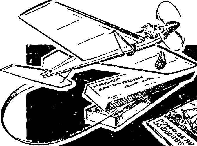
 A few years ago in the sale appeared first on new sets of blanks for the construction of cord aircraft. They came to replace the outdated (“Flight models” and “Models for air combat”), which modelistica domestic industry produced almost unchanged for decades. The novelty was the “one in three persons”. By changing only the wing span and small variations of the chassis developers managed on the basis of similar items to create and “pilot”, and “rumble”, and even “high-speed” sets. At least, that these names were applied to cardboard boxes with almost the same pieces and drawings…