 Control line model airplane. Analysis editorial reader mail shows that in recent years there has been increasing interest in modeling. We write and call the Pope in the memory of which still alive the memories of the numerous model clubs, the howl of the engines above kartodrome about the magical feeling of self-piloting flying models. All that they would wish for their children, but to introduce them to the modeling complicated, because a unified system of technical creativity is lacking today, and a few relevant institutions very rarely have the model aircraft clubs.
It should be noted that currently there are problems with the purchase as separate components for fixed wing aircraft, and fully prepared miniature aircraft. However, not all such models afford, and piloting of ready-made model for technical creativity to name difficult. That is why the parents are asking the editors to publish drawings and descriptions of a simple cord models, they could do with children at home.
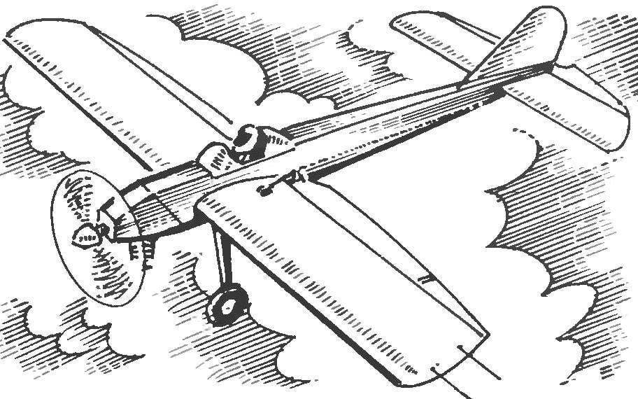
We offer our readers such a model. This is a simple training cord “pilotage” designed by the scheme of the low wing with a symmetric profile. Design made using balsa, basswood, pine and foam.
The fuselage of the model is rectangular with a frame of pine slats-spars a cross section of 3×3 mm and filled with packing foam, sheathed with plywood with a thickness of 1 mm, fixed to the frame with epoxy glue. In the front part of the fuselage glued under-eye frame made of beech slats.
Billet plywood sides of the fuselage at the first stage are cut without a cut-out under the wing — it is easier to do after Assembly of the fuselage. The frame of the wing, then glued the lime strip with a thickness of 2 mm, and the frame is fixed to the boss of lime fused into it by a nut threaded M3.
The wing is fixed to fuselage with beech pin with a diameter of 5 mm, which is when the dock is inserted into the opening in the panel of beech.
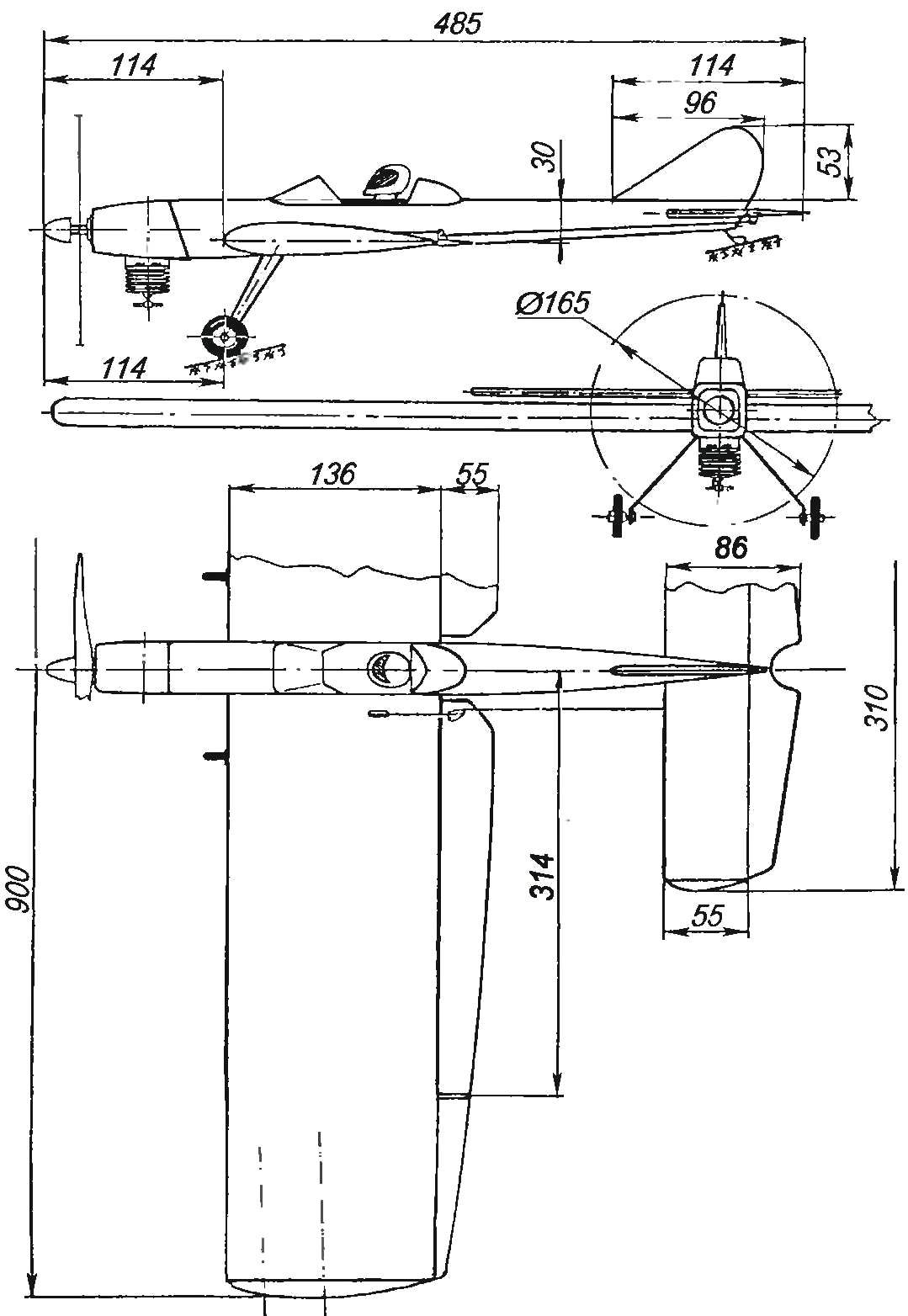
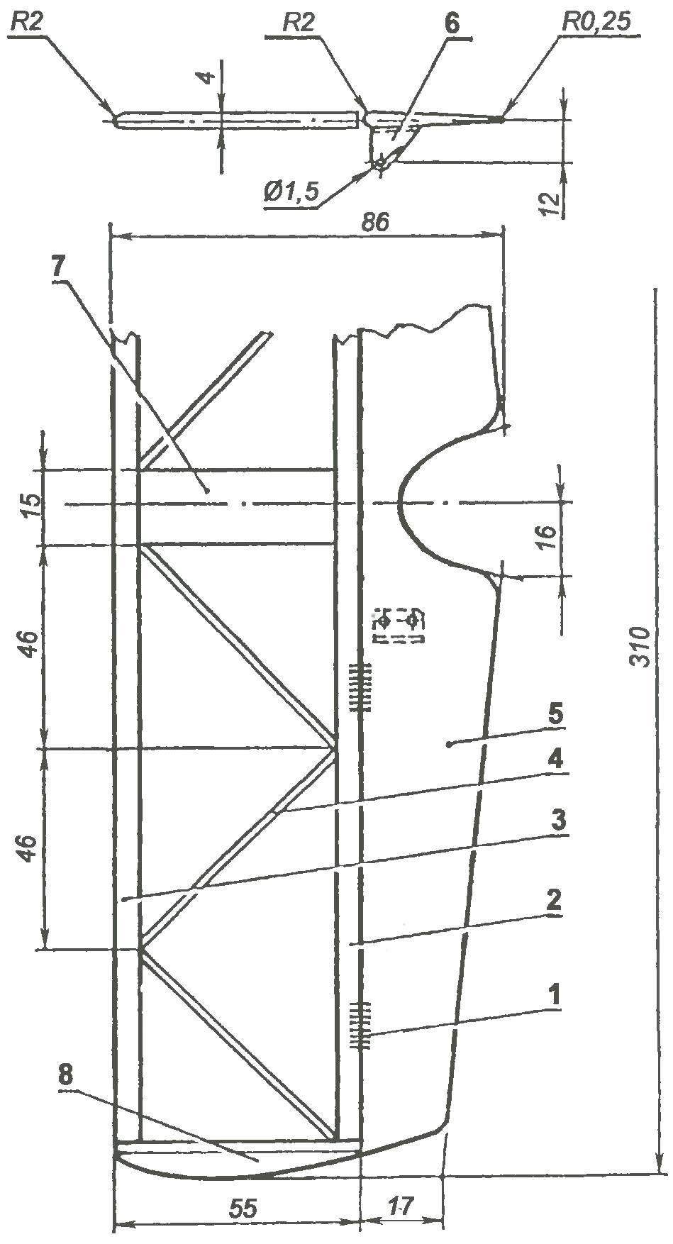
The geometric scheme of the pilot cord model engine MK-17 “Junior”
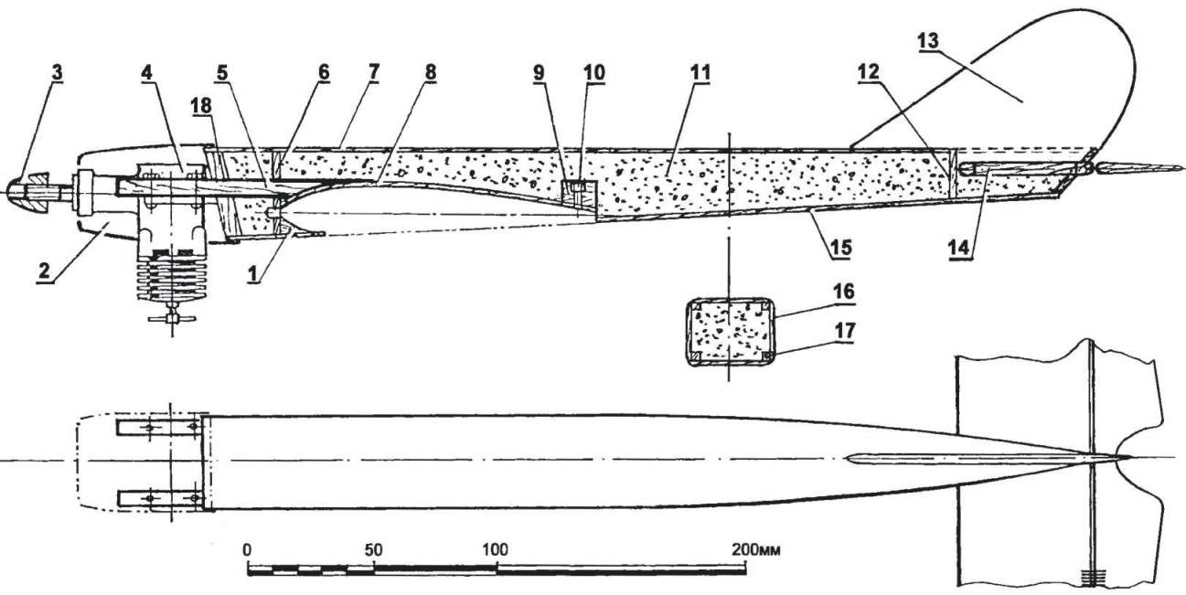
The fuselage of the flight model (on the top view the engine is not shown):
1 — insert (beech); 2 — hood (Vileika fiberglass); 3 — spinner; 4 — engine MK-17 “Junior”; 5 — sub frame (beech); 6,12 — formers (lime, s3); 7,15,16 sheathing (plywood s1); 8 — cradle wing (Linden, plate s2); 9 — boss (Linden); 10 — nut M3; 11—filling (foam plastic); 13 — keel (balsa, s4); 14 — stabilizer; 17, the longitudinal elements (spar) frame of the fuselage (pine, battens 3×3); 18 — power frame (Linden, plate s5)
The keel is fixed, it is cut from 4 mm balsa plate and fixed by glue in the tail section of the fuselage. The cross section of the keel is rounded in front of and eclipsing the “mustache” on the back.
Fuel tank, soldered in tin-plated sheet 0.3 mm thick, is mounted in the front part of the fuselage, directly behind the engine.
The assembled fuselage is polished with sandpaper, covered with microgrants, re-polished and painted with enamel. As the visor of a pilot makes sense to use a blank cut from suitable for color plastic bottle; headrest of the cab, from the fake block, the head pilot’s helmet — from a suitable plastic ball.
Horizontal tail, stacked, glued balsa and lime strips. After profiling and viskazivaniya frame is covered in metallic Mylar film on glue BF-2. The blade rudder is balsa, after manufacturing and painting they are connected with the stabilizer loops-“eights” of nylon thread. Between the blades is connected with a jumper wire-crosspiece.
A wing with a symmetrical profile, most suitable for models of this class. Its relative thickness traditional pilotage 16 per cent. Wing design — patterned lining — made of metalized Mylar film.
The manufacture of the wing is convenient to start with the preparation of ribs from balsa plates 3 mm thick, a pine front and back edges, as well as pine shelves of the spar, the Ribs will get strictly the same, if of sheet aluminum to cut two of the template to pull in between the long studs with nuts package balsa blanks and process them, periodically controlling the hull form with a flat metal ruler. The grooves for the spars and at the front and rear edges are cut with fine teeth with a hacksaw.
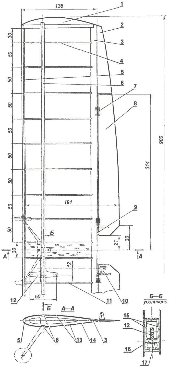
Wing:
1 — ending (balsa): 2 – extension of the chord of the wing (balsa plate s4); 3 — trailing edge (pine, rack 6×12); 4,11,14 — rib (balsa plate s3); 5 — the leading edge (pine, rail 4×4); 6 beam flange (pine, rail 3×6); 7 — loop (nylon thread); 8 — trailing edge (balsa plate s4); 9 — cross member (steel wire Ø2); 10 – horn control flap (made of anodized aluminum, the sheet s1,5); 12 rocking of the control system (duralumin, sheet s2,5); 13 – a lining of the Central part of the wing (Linden, plate s1); 15 wall boxes wooden (pine, 3×8 rail); 16 – axis rollers (steel, wire Ø3); 17 – remote sleeve (PTFE)
Horizontal tail:
1 — mesh; 2 trailing edge (Linden, rail 4×4); 3 — front flange (lime, rake 4×5); 4 — bracing (balsa rail 4×3); 5 Elevator (balsa plate s4); 6 — Elevator horn rudder (aluminum, sheet s1,5); 7— Central insert (balsa plate s4); 8 – ending (balsa)
Frame Assembly is carried on a flat Board. Original details are recorded on it with the help of pins, rubber rings and stationery clothespins, and after checking the Assembly precision and eliminate distortions seams are filled with epoxy glue, slightly diluted with acetone. At the end of the rib right of the console, between the shelves of the spar thread and glue attached lead weight with a mass of about 15 g.
Rocking control sheet duralumin with a thickness of 2.5 mm; it is mounted in the box is made of Linden slats, and between the first and second ribs of the left semi-wing.
Traction control dural with a diameter of 2.5 mm, it is easiest to make them out of knitting needles for knitting.
Cording wing metalized Mylar film is made with glue BF-2 and a small pressing on the classical model of the technology.
Flaps seleblitie, with the wing they are connected with hinges-“eights” of nylon thread. Between the flaps are connected by jumper-crosspiece of steel wire with a diameter of 1.5 mm.
Chassis model a spring, elastic element sheet duralumin with a thickness of 2.5 mm. Wheels, plastic chassis, rubber tires, and their diameter is about 30 mm, a width of about 12 mm. Mount the wheels to the spring — bolt with thread M3 and the corresponding nuts. For fastening the chassis to the wing in the past provided a fake bar with glued to it with two screws M3.
After Assembly it is necessary to combine the model’s center of gravity with the point corresponding to 20 — 25 percent of the wing chord, measured from leading edge. Makes sense in the process of making a model to produce the intermediate measurements of the position of the center of gravity, correcting if necessary, the weights of individual model elements. You can also shift on the fuselage location of the cutout under the wing, but if the alignment still will be different from the optimal, it can be offset with the help of cargo to the front or rear part of the fuselage.
I. SOROKIN
Recommend to read
 “MOSQUITO” WITH FEATHERS
Among purchase toys that can move (ride, swim, run, fly, crawl), it is not easy to find such models that can be safely run in the apartment without fear that they'll break, dropping to...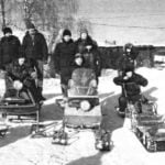 CAR SNOWBOUND
Snowmobiles and tracked metamagic — "heritage" the magazine of the circle of technical creativity "modelist-Konstruktor", in the village of Siwa Perm region. The first snowmobile created...
