TWIN-ENGINE ELECTROLET

TWIN-ENGINE ELECTROLETFlying cord “pilotage” — a beautiful sight, equally exciting for the athletes and spectators. Accordingly, among modelers-korovikov the number of adherents of flying is very high. And it could be much higher if not for problems with model aircraft engines. A small resource of internal combustion engines, the difficulty of obtaining fuel mixture, difficulty starting (especially in winter) — all of this contributes to the popularity of cord models with internal combustion engines in General and flight in particular.

That is why KOR-device constantly looking for a replacement engine and cranky all pay more attention to electric.


At present, it created a powerful and compact electric motors, and small power sources of large capacity that allows you to create kordovye model, able to perform almost all complex maneuvers.
 
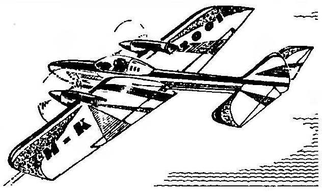
Today we will focus on the relatively simple twin-engine Cordova flight elektroleta.
 
The choice of the aerodynamic scheme of the model largely due to the relatively small capacity of available electric motors type DK-5-19. That is why the model is made with twin-engine. In addition to doubling the capacity of the improved airflow of the wing and flaps, which increased lift at low speeds, and stabilizer, which in turn favorably affected the maneuverability of the apparatus.
 
Wing elektroleta stacked design with a covering of Mylar film has a symmetrical profile Yak-55 (modified) with a relative thickness of 16.4 percent across the span (excluding the chord of the flap). This profile is most commonly used for aerobatic models — it has good bearing properties, and the nature of the stalling model with a wing of such profile is usually soft and smooth, which greatly simplifies piloting elektroleta.
 
The wing was assembled on a flat Board on which was fixed Plaz — sheet paper is made in 1:1 scale of the planned projection of this node model. After that, plasma was delayed with plastic wrap to set the wing are not stuck when assembling.
 
To improve the accuracy of the Assembly on the slipway is attached to two smooth rails at a distance of 110 mm from each other. Then with the help of pegs and pins were fixed front and rear edge of the wing, and the bottom shelf of the spar, then epoxy glue was set ribs.
After curing epoxy on the wing was installed the top shelf of the spar and a cladding of 1 mm balsa in the area of the plane of symmetry of the wing and in the locations of the engines. At the end of the frame right console fixed lead weight with a mass of about 15 g.
 
Rocking control, cut from fiberglass with a thickness of 3 mm, fitted with a pair of remote plastic bushings and steel axle with a diameter of 3 mm in the box, glued the strips of lime; the latter is mounted in the wing in the compartment between the first and second ribs.
 
The nacelle model is glued together from thin fiberglass and epoxy on a wooden disc, the cylindrical section of which corresponds to the diameter of the motor (in DC-5-19 — about 20 mm). Before forming blank isolated thin (food grade) plastic film, so you can remove the glue after curing epoxy resin. The finished shell was esquivels, fine-tuned in accordance with the drawing and glued with epoxy to the wing.
 
Geometry Cordoba flight models with electric drive
Geometry cord aerobatic models with electric drive
 
The fuselage
Fuselage:
 
1 — front cowl (balsa); 2 — frame No. 1 (balsa, plate s2); 3,17 — stringers (Linden, rail 2×2); 4 — cover plate (Linden, plate s4); 5 — frame № 2 (balsa, plate s2); 6 — upper wall (balsa plate s1,5); 7 — a lining of lodgement of the wing (balsa plate s1,5); 8 — frame No. 3 (balsa, plate s2); 9 — boss (Linden, gas-Tina s10); 10 — nut MZ; 11 —frame № 4 (balsa, plate s2); 12 — lateral wall of the fuselage (balsa plate 1,5 s); 13 — frame № 5 (balsa, plate s2); 14 — frame № 6 (balsa, plate s2); 15 — keel (balsa plate s3); 16,18 — the lower wall of the fuselage (balsa plate si,5); 19 — lower fairing (balsa)
 

Wing
Wing:
 
1 — ending (Linden, plate s2); 2 — trailing edge of the wing (balsa rail 10×5); 3 — panel (balsa rack 10×2); 4 — insert; 5 — trailing edge flaps (Linden, rake 5×2): 6 — the leading edge of the flap (lime, rake 4×2); 7— loop (nylon webbing); 8 — bracing the frame of the flap (Linden, rail 2×2); 9 — root rib of the flap (lime, rake 8×3); 10 — torsion (steel, wire OVS d1); 11—horn control flap (duralumin, sheet si); 12 — rib (balsa, plate s2); 13 —sewing Central part of the wing and mounting of the nacelle engines (balsa, plate s1); 14 — beam flange (pine, rail 5×2); 15 — fairing the lower part of the wing (balsa); 16 — anterior edge of the wing (pine, battens 3×3); 17 rocking of the control system (glass fiber, sheet s3); 18 — spacer sleeves (polyethylene); 19 — shaft (steel, wire d3); 20— wall boxes wooden (pine, rail 5×3)
 

Rotor installation Cordoba elektroleta
Rotor installation Cordoba elektroleta:
 
1 — spinner (polystyrene); 2 — propeller (d150, h = 150); 3 — motor DC-5-19; 4 — nacelle (Vileika of fiberglass and epoxy resin); 5 — wing

 
Installed in the nacelle motors DC-5-19 connected in parallel Litz wire cross section of 0.25 mm2 using soldering and connected to the conductive Kardam (again, by soldering). This used standard steel cords.
 
Thus prepared, the wing was removed from the pile, stripped and covered in a thin Mylar film on glue BF-6.
 
Flaps — stacked design, with their skinny frames Mylar film on glue BF-6. Wing flaps are hinged with nylon hinges.
The horizontal tail has the shape of a flat plate with a rounded front and straight rear edge. The stabilizer is assembled on the Board-the slipway. Cording – thin Mylar film on glue BF-6. Elevators seleblitie, with stabilizer, they are connected by nylon loops.
 
The scheme of constructing the profile of the wing
The design of airfoil
 
Table of the control section of the airfoil
The table control section of the airfoil
 
The fuselage pilotazhki cord having a cross-sectional shape of a trapezoid, made up of four walls (the balsa plate thickness of 1.5 mm) and six ribs (2 mm balsa plate). At the bottom of the fuselage joints are strengthened with stringers — fake reek a cross section of 2×2 mm. Fixed the rudder is cut from a 3 mm balsa plate for relief has cutouts. Before the second (counted from the nose of the model) a frame attached cover plate with a hole of 5 mm diameter under the pin-lock wing. After curing the epoxy adhesive in the area between the second and third frames of a notch under the frame of the wing, before the third frame fixed boss with a glued in nut MZ her (it joined the fuselage and wing) balsa strip 1.5 mm thick sealed cutout under the wing cradle. Front and lower fairings bow — seleblitie, lightweight (thickness 2-3 mm). After sanding the fuselage primed and painted by nitroenamel. The keel is covered with Mylar film. Lantern “cockpit” cut from a clear plastic bottle of shampoo, head of the “pilot” and the headrest “seats” made of painted foam.
 
Chassis spring type arched steel wires, allied with a diameter of 1.5 mm landing gear Wheels with a diameter of 25 mm cut from a dense foam stamps PVC; wheel bushing is a plastic tube (cut refill gel ball pen), and instead of the tyre on the wheel is wound a few turns of vinyl electrical tape. Chassis attached to the wing using the balsa fairing in which the slotted recess under the curved Central part of the spring.
 
The propellers have a diameter of 150 mm at a step of 150 mm. as for the maneuver model it is best to have a propeller setup with counter-rotating propellers, it is, of course, reflected in their form — propellers mirror-symmetric. They are cut from basswood on the type of those installed in high-speed cord models.
 
The power cord of electric motors models — 12-volt motorcycle battery capacity 12 Ah, which is located behind the athlete in a small school type backpack. The control stick model is sawn from 12-mm plywood; in its upper part, where the control is the thumb of the right hand of the athlete, set the switch engines. To Kardam, around the points of their attachment to the control handle, soldered the ends of a strong cord; their free ends are equipped with connector, which connects to them and the battery.
 
Adjustment of elektroperedachi cord was reduced . the cutting blades of the propellers with the test model after each operation. It was measured the symmetry of right and left traction motors with suspension model on rubber thread-rotor settings down. Launching in turn the right and left motors, can be qualitatively (and, optionally, quantitatively) evaluate the thrust of each of them. After achieving equal and optimal thrust propeller systems propeller blades to balance, polished and covered with parquet lacquer.
I. SOROKIN

Recommend to read

  • UNKNOWN CELEBRITYUNKNOWN CELEBRITY
    Flying boat POTEZ 452. In the early 1930-ies of the French aviation firm Aeroplanes Henri Potez ("Aeroplanes Henri Poteza") built a small flying boat Potez 452, which has become one of...
  • “GOAT” IN THE GARDEN“GOAT” IN THE GARDEN
    Memories of childhood and adolescence accompany the person in his life: about the native log house with a Russian stove; the sun warmed the dusty paths of the garden, the goats (most of...