UNUSUAL “BOUZOUKI”

UNUSUAL It would seem that all has been investigated in this technically simple class of models, as F2D (combat model aircraft). But no, from time to time there are new developments designed to bring to perfection, if not the entire structure of the apparatus as a whole, at least the main nodes. Today we bring to the athletes is very innovative solution to this important hub, as the wing tip. If other aeromodelling classes when rendering first tackle the issues of aerodynamics, the “bouzouki” is much more important than their minimal weight and the ability to effectively combine the front and rear of the power zone of the frame together. The latter factor is important not only in extreme situations. At the same time provided a good connecting construction of the said belts, and wingtips will be significantly easier and the whole power structure as a whole.

Traditionally ending on modern machines (regardless of the “flying wing” or polosamota scheme with imposed horizontal tail) are glued together in a T-shaped profile, two balsa plates with average chord near the wing tips of about 200 mm. There are many other ways but the most common due to simplicity, manufacturability, reliability, and used by athletes for more than two decades.
 
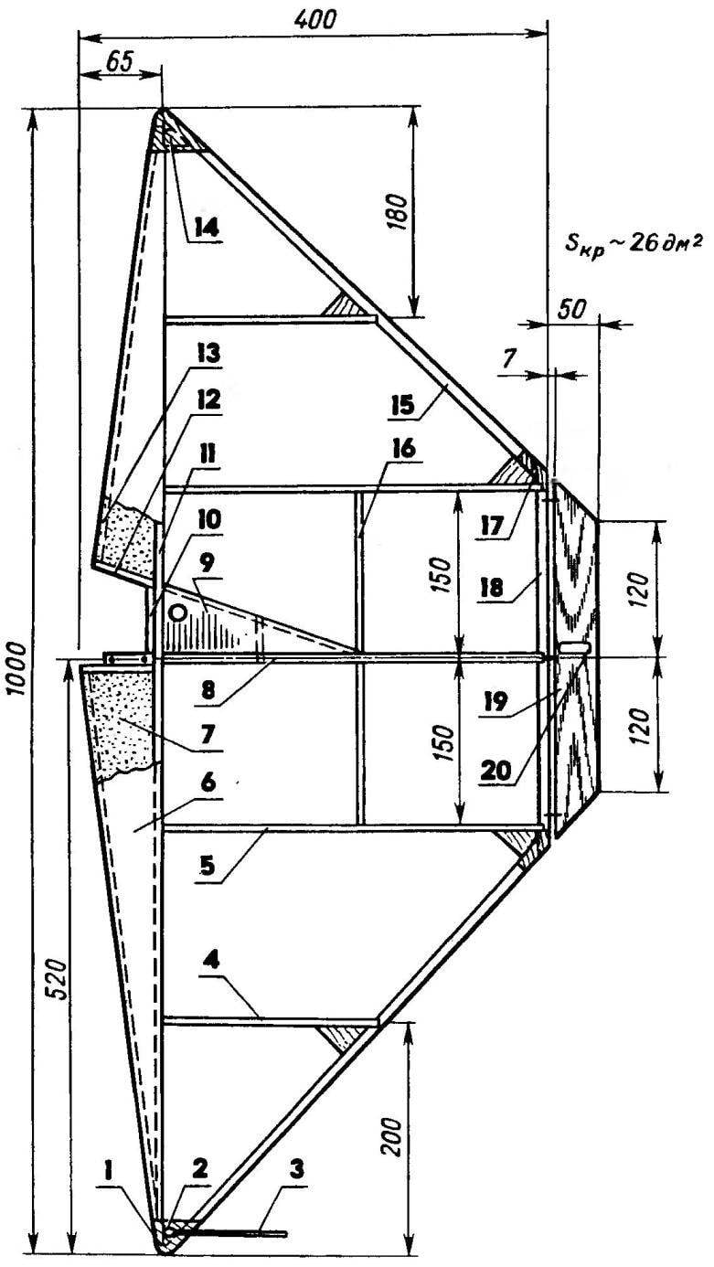
However, it seems that he was more than a worthy competitor. The essence of design of a novelty — almost… the complete rejection zakonopacheny nodes as such. The proposed modifications to the front and rear of the power zone-the edge of the frame of the wing are brought together and tied a small scarf of thin plywood top and bottom wing and struts of fake plates with a thickness of 2 mm from the intermediate ribs. Thus greatly increase frame strength — now a power contour of the wing is a very tight triangle, and is pliable, a ladder of ribs, the tips and edges.
 
Of course, this design has its disadvantages. So, with the existing limitation of the scale up to 1000 mm triangle causes a sensitive loss of bearing area near the ends of the consoles. However, it’s not terrible — if you want the area restored to the standard borders by increasing the trailing edge or the elongation of the Central rib (last admission many athletes directly associated with improved maneuverability “bouzouki” and reduce “hysteria” of her behavior in the maneuvers). There is another point in favor of the new solution. It had already been agreed the possibility of reducing mastela it is not necessary to translate it into the rate model. After all, there is another good use of these surplus — improving traction characteristics of the plant. This is achieved through slight modification of the propeller by increasing its diameter or slightly reduced geometrical step. In any case, this change will give a slight increase in flight speed with the tape speed reduction without the tape, and (most importantly) significantly reduce the slowdown when executing the series of sharp maneuvers in battle.
What can result is a new approach to the design of the wing tips on fighting models, can be clearly seen from the drawings. Although there are other designs, even in these markedly General simplification of construction, resulting in an increase in the stiffness of the frame, simplification of technology of its manufacture and to reduce the mass of the model.
 
It is noticeable and the desire of the designer to solve two more problems that inevitably arise with virtually no developed along the chord of the winglets, — identify the location and technical design of the node output cord control outside of the wing. On models with the external location of all the controls to make it not so difficult. The difficulties begin with the traditional location of the rocking and the driver wires inside the cavity of the wing. Need to think about how to hold cords or cables through the back edge, without violating its overall strength. It is desirable even minimal weight to the left wing console, not to compensate the extra weight of lead on the right ending.
 
Control line model air combat under the engine working volume of 2.5 cm3 (championship class)
 
Cord model air combat under the engine working volume of 2.5 cm3 (championship class):
 
1 — the gusset plate connecting the left node (plywood s 1), 2 — M3 screw for the mounting bracket output cable routing management 3 — bracket (steel wire diameter 1,2), 4 — rib (balsa plate s3—4 or fake s2—3), 5 — rib basal, 6 — sheathing foam forehead (paper for recorders on the PVA glue), 7 — head (foam stamps SS-4-40 quality or packaging), 8 — rib with the Central engine mount (Assembly Assembly) 9 — Klondike solitaire to enhance the sub part and for the formation of the padded compartment of the fuel tank (balsa plate s3), 10 — power bulkhead (plywood s1, 5), 11 — shelf spar embedded into the foam of the forehead (pine rail 5×4), 12 — the root overlay foam forehead (balsa plate s3), 13 — edge of the front (lime or balsa plate with a thickness of 3 to 4) and 14 of the gusset plate connecting the right node and the load of lead 15 g, 15 — flange rear (pine rack 8×4), 16 — spar auxiliary, 17 — gusset plate connection, the rear element of the edge (s1 plywood to put on top and bottom), 18 — Central portion of the rear edge (pine rack 10×4), 19 — Elevator (balsa plate s4), 20 — podkovalnikov trim (plywood s1).
 
Central power node model (view from the side of the engine)
 
The Central power node of the model (view from the motor side):
 
1 —edge front, 2— under engine cover plate foam forehead (fake plate s3), 3 — Board motor (Linden or beech plate s12), 4—shelf side rail, 5 — power bulkhead (corresponding to POS. 10 the previous figure, but as a option is made from lime plate s5), 6 — axle suspension rod outer control arms of, 7 — shelf a Central rib (Sosnowiec 12×3), 8 —spacer ribs, 9 shelf support spar (pine rake 4×2), 10 — the wall of the auxiliary spar (balsa or foam), 11 — a lug back (fake plate s12), 12 — edge of the rear, 13 — hinge suspension of the Elevator 14 is the wheel height.
 
 
Cord model air combat under the engine working volume of 1.5 cm3 (school subclass).
 
Diagram of the device for armoreska foam billet head wing
 
Diagram of the device for armoreska foam billet head wing:
 
1 — base 2 — mounting bracket fixed end “strings”. 3 — calibration sub-block lining foam billets 4 – terrorise element- “string”, 5 — template of the root rib, the 6 — conductor for applying a voltage to the “string” is a flexible, 7 — arm, 8 — arm spacer insulating.
 
Central power node model (view from the side opposite to the engine)
 
The Central power node of the model (view from the side opposite to the engine):
 
1 — power ledge (beech plate s12), 2 — radical strip of foam forehead (fake plate s3), 3 — shelf side member (pine rail 4×3), 4 — longitudinal closing wall (plywood of 1.5 s or fake plate s3), 5 — screw fixing the fuel tank 6 — fuel tank, 7 — headstock internal rocking control 8 — rocker control, 9 — shelf Central rib (pine or Linden slats 12×2), 10—strut rib, 11 —a lug back (Linden), 12 — flange rear with pads, 13 — the Elevator (balsa plate s3).
 
Fuel tank
 
Fuel tank:
 
1—supply pipe, 2— pipe drain-filling (at the same time is used during operation of the engine for pressurization of the cavity of the tank), 3 — M3 screw for mounting the tank on a Central rib (soldering from the inside of the tank before Assembly), 4 — pot (soldering of tinplate s0,3).
 
Rocking chair
 
Rocking control.
 
Note that “bouzouki” school of subclass is larger than traditional scale models will never performed. Thus it was possible not only to get rid of the effect of loss of bearing area in the absence of endings, but leave the leashes cord at the same distance from the Central axis of the model. Again we focus your attention on sverkhprovodimosti models in General — if desired, and simultaneous modification of the shape of the rear edge in the form of a net or faceted powellii such a scheme can be successfully transferred to the sports class.
Everything else is interesting and the opportunities for dramatically simplifying the technology cutting foam blanks for power lobikov wings. In the usual scheme of work we have to keep track of thermolabile simultaneously by two profiled patterns of the profile of the sock of the wing. In the absence of much experience (or very intricate lever devices, which usually do not guarantee high-quality cut) this process is not only complicated but also inefficient because of the large percentage of marriage. Because the slightest unevenness of strings, or asynchronous stroke it along the contour of the templates lead to the bumps and depressions on the surface of the resulting foam blanks or to General distortion of the taper profile. In our case, the whole situation is extremely simplified due to the lack of one of the templates as such. In fact, it is the role of the height-adjustable stand with heat-resistant insulating head for attachment of the fixed end of the strings, and the calibration lining, which is a block of foam blanks. Around the rest of the template cutting thread easily fortified even alone, without an assistant, and cutting of blanks goes without marriage and turns into a genuine pleasure.
 
The rest of the construction sites of the proposed “bizovac” is quite traditional and does not require any special explanation. So if you like the new scheme, you will be able to easily implement it in real design.
 
V. YAKOVLEV,
master of sports,
Moscow

Recommend to read

  • SCREW IN SUPPORTSCREW IN SUPPORT
    Of course, the wooden parts connecting screws — most reliable. But as the load places on the legs of chairs, doors loop — hole is gradually being developed; the same occurs with the...
  • PARITEL ‘ CLASS A1PARITEL ‘ CLASS A1
    The proposed model glider created based on ideas... not to be used as a construction material balsa and composite materials. The supporting plane of the apparatus — traditional design....