Note the drive system of the flap-ailerons. As shown, such meghrashen nodes fully protects the elements of the frame and servos if the alarm reset wing when cut nylon M4 screws securing the rear edge.
The fuselage is of rectangular section with working plywood covering. When drawing the special attention was paid not only to reduce its mass, but also manufacturability, allows you to build a good fuselage even in unsuitable home. Please note — almost all the lines formed by completely straight lines, with the exception of a short section of the bottom of the bow, and the sides are parallel to each other. This solution allows to increase the accuracy of manufacturing of the patterns of skins. After the recess the plywood blades with a ruler is much more accurate than cutting out a jigsaw, requiring subsequent filing of the edges. Improved connectivity of individual parts will increase the strength of the entire frame, therefore, the fuselage will be possible to save a lot of weight on the adhesive seams. Lower valance flat adopted not only for reasons of aesthetics. First of all it is the base on which elementary exhibited the set. Yes on a ready model, the same base will allow the most precise way to set the wing and stabilizer without using any additional measuring devices, supports, brackets.
The fuselage does not require special explanation, it is only necessary to note that the thickness of the sidewalls from the rear edge of the wing should be gradually reduced. The tail is two layers of three-layer millimeter plywood.
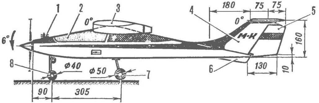
The tail unit made by T-scheme. Although it causes increase of mass of the keel carrying a stabilizer for training a model can be considered more preferable. The fact is that emergency landings are not uncommon when flying with beginners, a T-tail stabilizer protects, provided that the model meets the ground, at least not up wheels. While such a scheme reduces the likelihood of the stabilizer in the vortex trail of the wing. Mount the horizontal stabilizer nylon screw, cut away at excess loads, in large measure, protects the stabilizer from damage.
The basic version of the training of radio-controlled models are based on the use of domestic equipment radio “Suprana-82” with four steering servos and motor “rainbow” glow variant working volume of 7 cm3. The capacity of the fuel tank for that motor should be at least 150 см8, according to the scheme he introduced on aerobatic models (see “M-K” № 1, 1983). If you debug the actions of the servos make when fully withdrawn to its outermost position the rods of the respective rudder is deflected to the corners of the: rudder ±25° Elevator ±15 ‘, the ailerons ±20°, lever controlled carb should not become a PA focus to extreme positions. In the version with the “Rainbow” is the mass of the model can be equal to 1900, then its takeoff and landing characteristics allow it to start even with the hands.
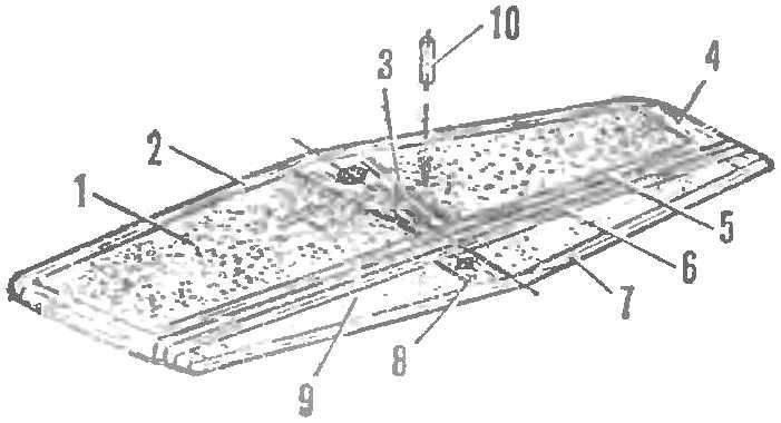
Fig. 5. The design of the stabilizer:
1 — filler stabilizer (packing foam), 2 — front flange (lime 3X5 mm). 3, the Central rib (lip thickness of 5 mm), 4 — ending (Linden), 5 — trailing edge (Linden 3X5 mm), 6 — the leading edge of the rudder (Linden 3X5 mm), 7 — trailing edge (Linden 3X5 mm), 8 — lug mounting pylon (Linden), 9 ‘ — placeholder booster (packaging foam), 10 — pin (beech, Ø 3 mm, seal).
R and S. 6. Mount Chasovoy landing gear:
1 — pins (OVS wire Ø 3 mm) 2 — front (wire OVS Ø 4 mm), 3 — bow frame.
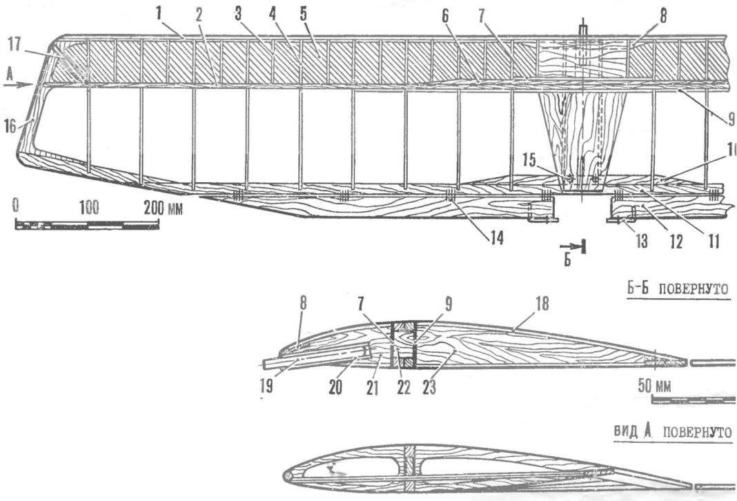
R and S. 7. Wing design:
1 — front edge pine (6X6 mm) 2 — shelf side member (pine 6X6 mm), 3 — Polonnaruwa (plywood 2 mm), 4 — rib (plywood 2 mm), 5 — skin of forehead (double layer Whatman), 6 — strengthening of the spar (pine 6 X X6 mm). 7 — the front wall of the side member (plywood 1 mm between the ribs), 8 — strengthening the front edge (3X10 mm), 9 — rear wall of side member (plywood 1 mm between the ribs), 10 — strengthening the rear edge of the pine (3-12 mm), 11 — the rear edge of the pine (3X12 mm), 12 — flap-Eleron (lip 4X30 mm), 13 — pin control (OBC wire Ø 1,5 mm) 14 — hanging of the flap-Aileron (nylon yarn), 15 — holes for screws fixing the back edge krila on the fuselage, 16 — ending (plywood 3 mm), 17 — end polonaruwa, 18 — sheathing chinoy center part (1 mm plywood), 19 — pin (beech Ø 7 mm), 20 — tube installation pin (D16T Ø 10X1,5 mm), 21 — boss (Linden 20 mm thick), 22 — corner of the junction of the side members (Linden, 12 mm thick), 23 — root rib (plywood 2 mm no relief).
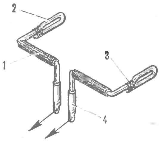
R and p. 8. The intermediate node of the control flaps-ailerons:
1 — tube-hinge (copper, wrap the threads with glue and set under the fuselage skin close to the part 36, Fig. 2), 2 — kavacik (OVS wire Ø 2 mm), 3 — winding copper wire (soldering), 4 — termination pig (copper tube, solder the end to flatten).
In the drawings is shown another modification, significantly lightweight compared to the first. The reduced weight of the model flies well with compression Microdrive KMD-2,5.
The volume of the fuel tank may be reduced to 80 cm3, with a view to further simplification of the apparatus, as it has only two servos: Elevator drive and rudder (the latter can be combined with active ailerons or completely go to manage, zakoniv the rudder in the neutral position). The main structural change of the simplified method are as follows.
Section stringers of the fuselage is made rectangular in contrast to the triangle on the main option. This, taking into account the lower power of the engine, more than two times to reduce the area of the plywood skin of the fuselage, to get rid of the additional reinforcement sheet of plywood, leaving a single trim until the bow, use one and a half times thinner plywood on the frames. The transition to a diagram of the chassis without the nose gear, the lower sections of the slats of the bed wing and the engine mounts will also give a considerable gain in weight. Nebritymi the remaining sections of the frame of the fuselage upholstered the same as the wing (it is, of course, has in this embodiment, the rigid skin of the forehead) Mylar film with prillerova top macalintal paper. Kiel, who became stacked, designed like a new version of the stabilizer. Lightweight tail section of the model compensates for the decrease in the mass of the bow, carrying the lightweight engine, the additional alignment of the device is almost not required.
As it turned out, the flights on this model, with minor specific strain, allow you to perform even the rapid ascending maneuvers without losing speed. The only disadvantage of this modification is increased sensitivity to strong wind, is due to the lower load and speed of flight. In good weather, great flying otopleniya modification with a low-power engine working volume of 1.5 cm 3. Here, the landing gear is better to completely abolish, replacing light wire “ski”.
D. ALEKSEEV, the master of sports of the USSR
 To the journal is receiving increasing numbers of letters from modelers who make their first steps in the class RC. And, as a rule, one request — publish a description of the glider or plane for the initial training. Increased attention to the units of this complex model aircraft class is clear — the domestic industry began to produce proportional radio control systems, and the achievements of modern radio electronics, in particular the emergence of new circuits, give the opportunity to build a good improvised equipment. Published drawings and a description of the “flying coach”, an interesting series of design solutions that allowed to create a universal multivariate training model. It is made entirely of domestic materials.