
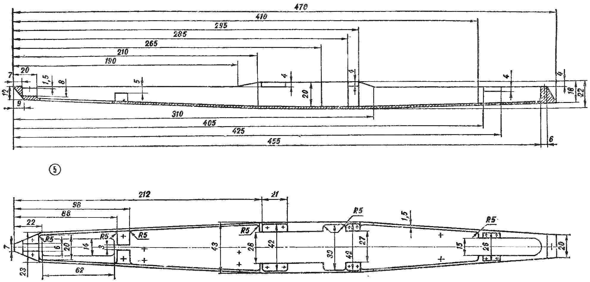
 High-speed cord model presented on these pages, designed and manufactured in the older group of avtomodelistov club for young technicians Novosibirsk plant named after V. P. Chkalov. A compression engine “meteor” with a working volume of the cylinder is 2.5 cm3. The lower part of the body — tray is milled from a block of duralumin brand D16T. Upper half — fairing — laminated of fiberglass in epoxy resin, processed for leveling the surface with emery paper and painted with synthetic enamel.
Front suspension pendulum consists of a body, two wheels, axle, mounted in ball bearings 5X13 (No. 1000095), and a spring strut. The relative position of the parts shown on the Assembly drawing.
Wheel model with non-separable type devulcanization on discs with a layer of rubber. The inside of the wheel (disc) machined on a lathe from duralumin D16T. The hole for the bearing is filled with wax or other material that do not react with lye, which then lowers the disk. The residence time in the bath depends on the concentration of the solution. After chemical treatment the surface becomes porous and vulcanization of rubber is well connected. A rough surface can also be obtained by sand blasting. Prepared the drive and lay the raw rubber in a mold and vulcanized. Then the diameter of the drive wheel is adjusted on a lathe to the desired size. Before installing the wheel on the model the tire balance.
The model has a sprung gearbox. This is a complex and responsible node, the quality of manufacture and Assembly of which will depend on the reliability and durability of gear pairs.
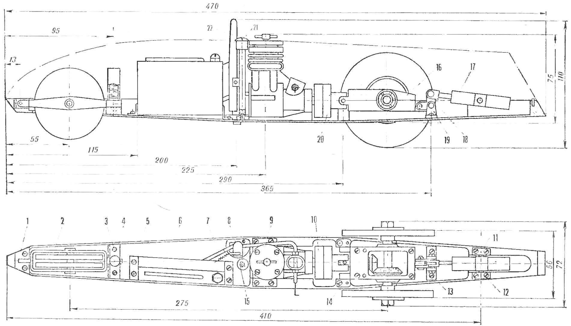
Racing car engine MD-2.5 “meteor”. Cord strap and the upper fairing is not shown:
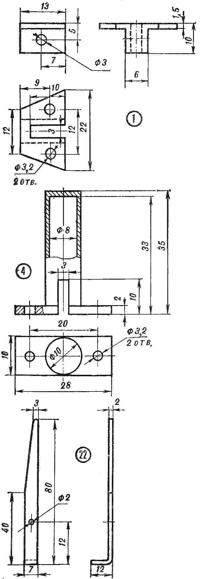
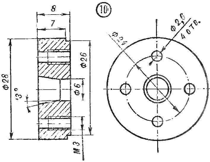
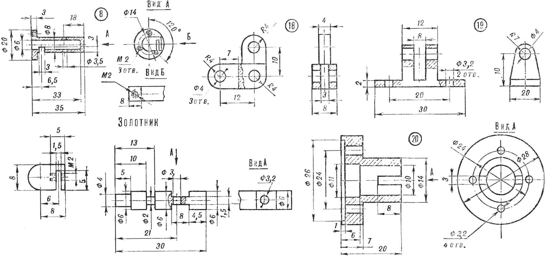
1 — front hanger bracket, 2 — front axle, 3 screws M3 and 4 — body front shock absorber, 5 — pan, 6 — fuel tank 7 — spring 8 — the case of bus devices. 9 — engine, 10 — handwheel 11 — axle shock-absorber, 12, 13 — the screws M3, 14 — axle gearbox, 15 — mounting bracket upper fairing, 16 — gear, 17 — rear shock, 18 — the rocker 19 — rear mount bracket, 20 — faceplate u-joint, 21 — screw mount body 22 antenna stopping device.
Pan (space holes marked in the drawing by a + icon, marked in accordance with the set details).
The gearbox housing is milled from duralumin D16T and has a connector on a horizontal plane. Half tight between the four M3 screws and is fixed against lateral displacement by steel pins. The driven gear fixed to the axle by welding. Seat face piercing holes under hole diameter driven gear, then napresovuyut it and welded. Turning treatment is carried out in the centres to the dimensions given in the drawing, with allowance for grinding 0.5 mm… Mount leading six similar to that described above. The axle and gear Assembly prior to grinding is subjected to hardening by high frequency currents to a hardness of 40-50 HRc.
For mutual running-in of gears in a reducer assembled on the working surface of the teeth will mow a few drops of oil suspension of diamond, corundum or carbide-Beren powder. After pressing the gear is washed in kerosene and set a new bearing.
Ball joint gimbal quenched to high hardness and fixed on the shaft drive gear steel pin through the cross hole.
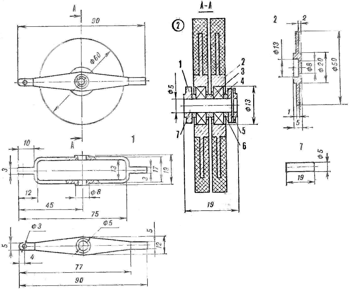
Front axle:
1 — body, 2 wheel drive, 3 — spacer, 4 — bearing, 5 — pin locking, 6 washer, adjusting, 7 — axis.
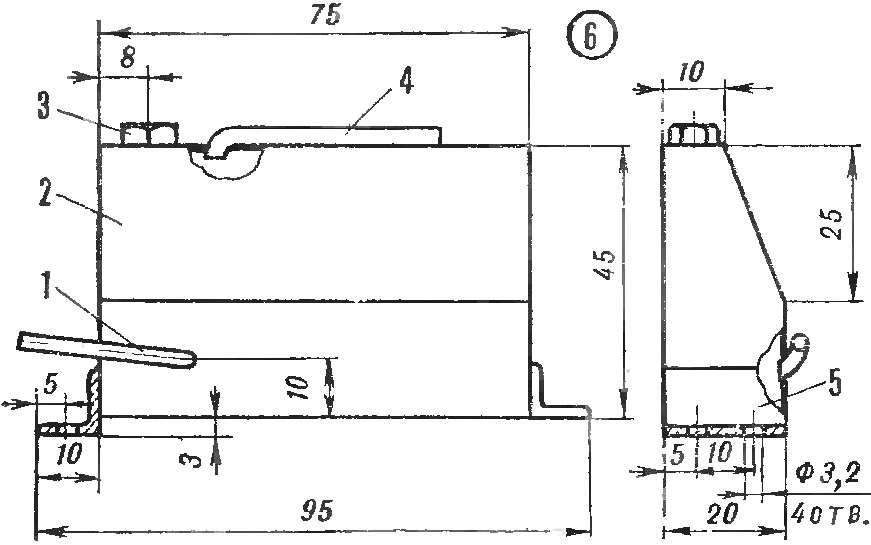
Fuel tank:
1 — supply pipe, 2 — tank 3 — fuel filler neck, 4 — drain pipe; 5 — area.
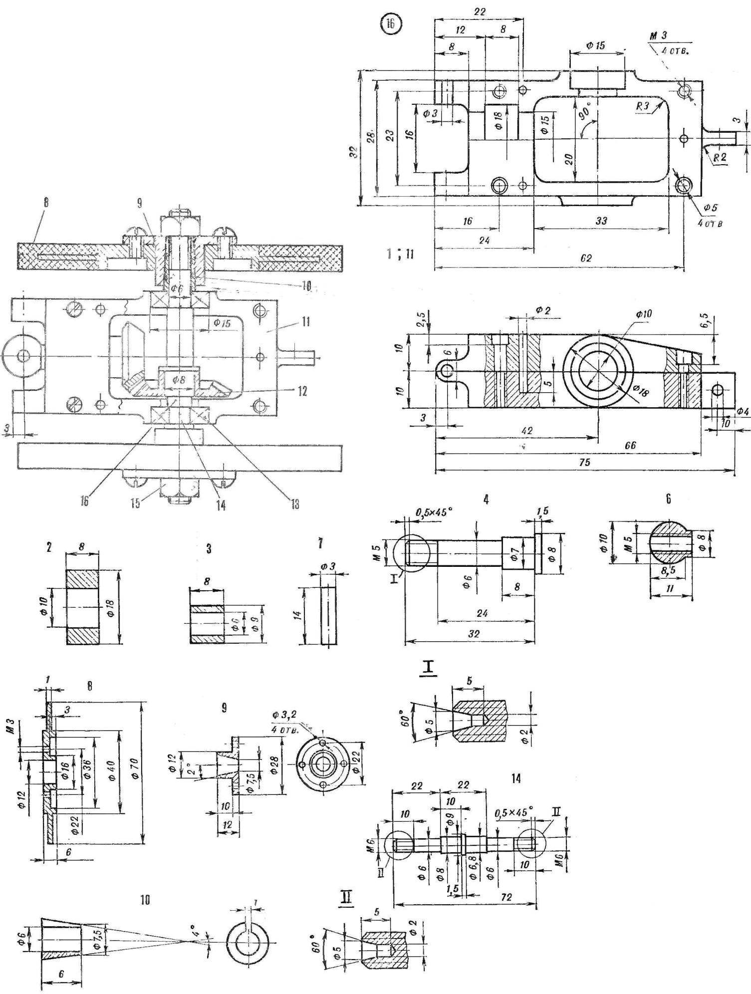
Gear:
1 — body, 2, 3 — spacer, 4 — shaft, 5 — pinion, 6 — ball Guk (the pin hole is drilled after the final adjustment of the bearings), 7 — finger, 8 — tire-wheel 9 — wheel hub, 10 — cone 11, the lower part of the housing, 12 is the driven gear, 13 — bearing 14 — shaft 15 — Ganka, 16 — spacer.
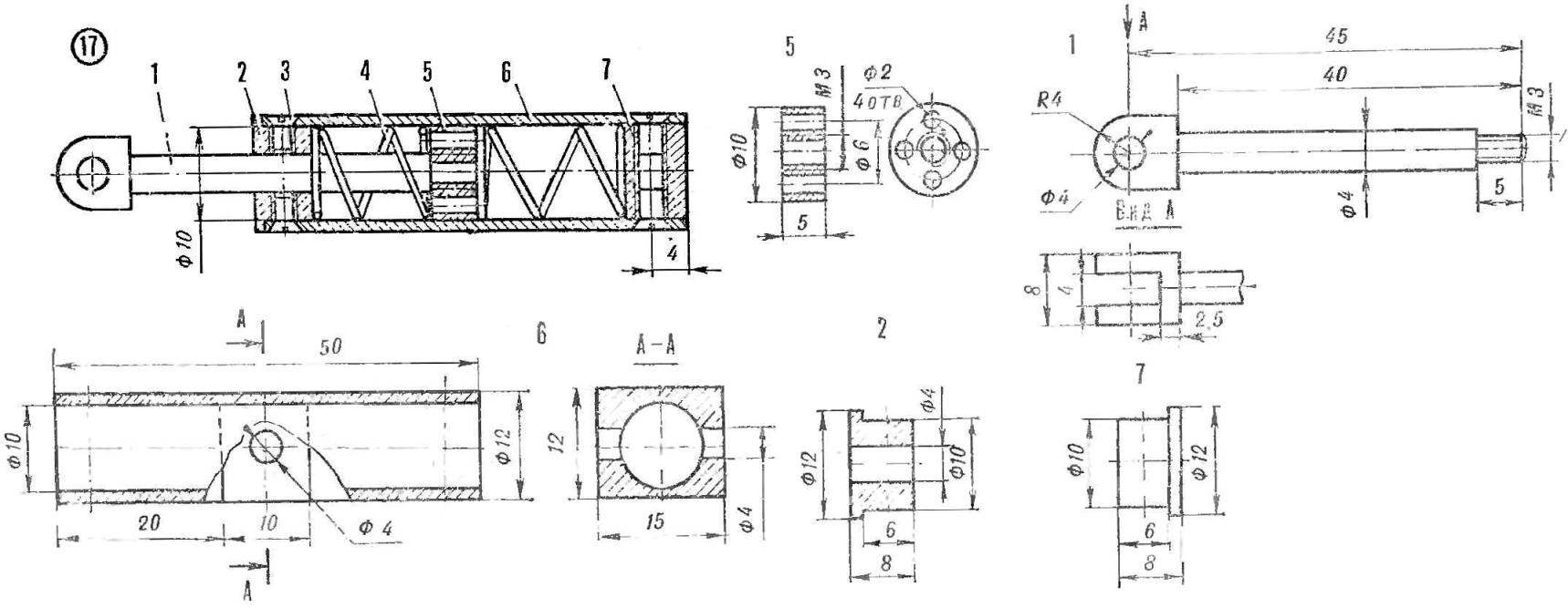
The rear shock absorber:
1 — stock, 2 — bushing (drilling and tapping produce, together with the cylinder), 3 — M3 screw, 4 — spring, 5 — piston, 6 — cylinder, 7 — cap.
The drive wheel hub is installed on the axis of ka polarising cones, providing secure mounting and quick removal.
Fuel tank, open type with one drainage tube and a fill port with a threaded plug. It is made of tinplate, connecting a separate part of the soft tin solder POS-40.
A stopping device operates on the principle of the contraction of the supply tube and controlled by an antenna derived from the model.
V. EFIMKIN, head of the society, Novosibirsk, Russia
Recommend to read
 FLIES LIKE A REAL
Many Teens are addicted to in summer camps and aeromodelling clubs the production and launch of thermoerosion, or as they are called, balloon-balloons filled with hot air. Anyone who... VAZ-2118 “the guelder-rose”
A new family of cars VAZ-2118 "the guelder-rose" is only the third in 35 years of existence, the Volga automobile plant — after "penny" VAZ-2101 and "chisel" VAZ-2108/2109 — really new,...
