Since 1987, entered into force new “Rules for flying sports in the USSR”. Changed and technical requirements for model rockets. So, in the category B4 (model raketoplana) one of them says: “In the case of models with a flexible wing of the planning part should be more than 50% of the starting mass of the model”. As practice shows, the innovation did not deter the athletes from the construction of miniature gliders, forced to look for new ways of their technical improvement. In our opinion, taking into account the new requirements are a very promising model with Delta wing, designed by athletes from the Moscow city Ramenskoye A. Levin and I. Prikhodko.
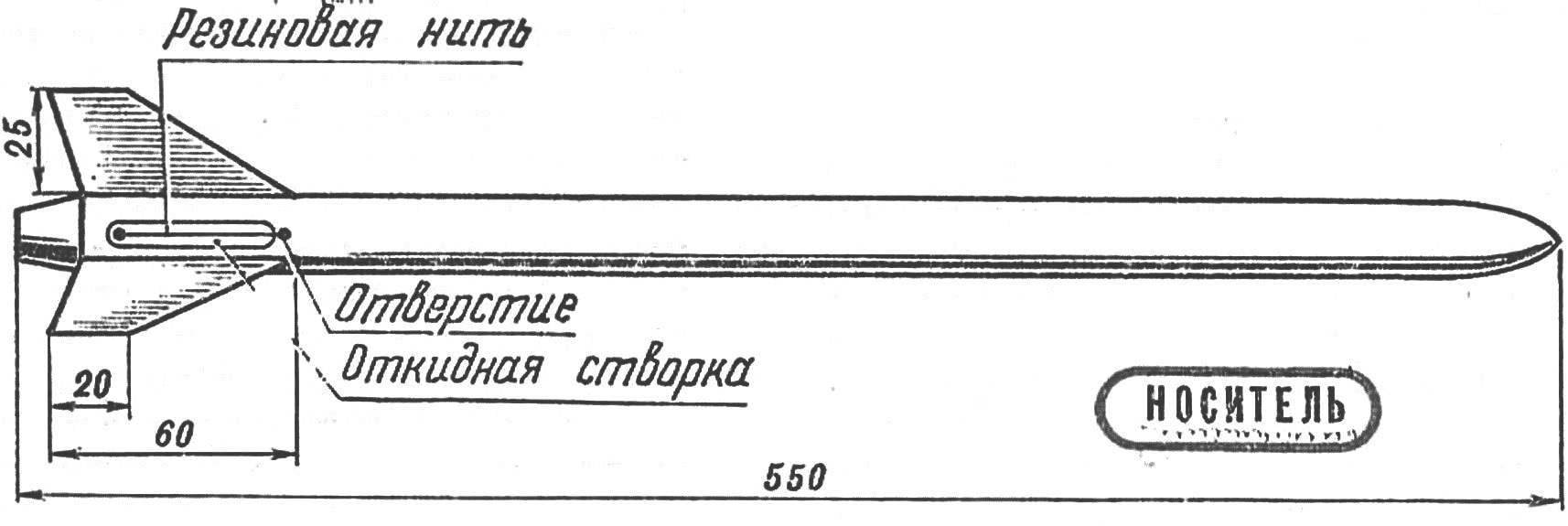
The planning part of the model performed according to the scheme “rogallo”, shot with rubber shock absorber. Thus the exhaust motor is on the “glider”.
The Central beam of the rocket with the pine rail D 4 mm, the end section decreases. In the front part of the beam is fixed to the spring hinge wire, 0.6 mm. 0 allied To his free shoulder thread with glue attached the side member (pine slats of variable section, the highest D 3 mm). Sweep angle of main wing on the side beams is equal to 120°.
The rear end of the Central beam carries a small hook, and at a distance of 45 mm from the forward edge on the sheet metal hinge hinged to the Central beam of the slat, the side “beams,” which represent a nylon yarn. The sweep angle of the slat — 70°, it is set by the binding threads of the edges to the side beams of the main wing at a distance of 200 mm from their ends.
 Since 1987, entered into force new “Rules for flying sports in the USSR”. Changed and technical requirements for model rockets. So, in the category B4 (model raketoplana) one of them says: “In the case of models with a flexible wing of the planning part should be more than 50% of the starting mass of the model”. As practice shows, the innovation did not deter the athletes from the construction of miniature gliders, forced to look for new ways of their technical improvement. In our opinion, taking into account the new requirements are a very promising model with Delta wing, designed by athletes from the Moscow city Ramenskoye A. Levin and I. Prikhodko.