 Training RC model airplane. This publication is for those who have sufficiently mastered the piloting cord model airplanes and thinking about the next step — creating the RC. You can, of course, buy ready-made miniature replica of the aircraft and start its development, however, great pleasure from it is unlikely to get made with your own hands and independently adjusted and test flown the model is not interesting example. And cost is cheaper to buy will have only the remote control equipment Yes servos.
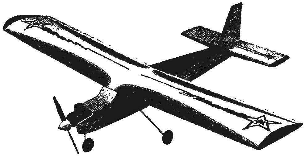
We offer young pilots a simple RC model of the aircraft, which will help quickly learn not only the takeoff and landing, but many of the figures of the aerobatics aircraft.
The apparatus was designed for polutorametrovy the engine, so special attention was drawn to observance of culture weight It ideal weight — about 500 g (without engine and equipment), so the main materials were balsa and foam. Pine and plywood were used in small quantities.
Aerodynamic design of the model is high. The wing has a PLANO-convex profile with a relative thickness of 12%. Engine MK-17 “Junior” with a volume of 1.5 cm3. Should be warned that in case of excess mass to more than 100 g, it will have to install a more powerful motor, for example, KMD-2,5.
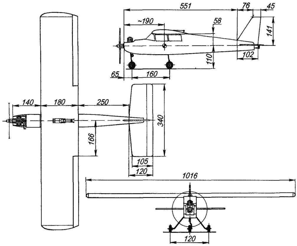
The geometric scheme of training for RC model airplane engine MK-17 “Junior”
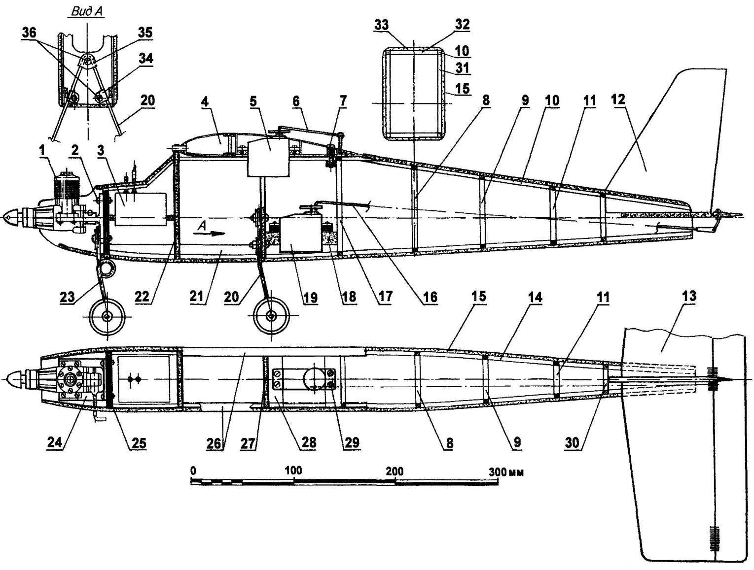
Model design (for the planned projection of the wing 4 and the upper casing 33 is not shown):
1 — engine MK-17 “Junior”, 2 —M3 bolts and nuts fastening engine mounts, 3 —fuel tank capacity 60 ml (tinplate s0,3); 4 — wing; 5 — servo actuator Aileron, 6 – drive rod ailerons (dural needle Ø1,5); 7 — screw M5 wing mounting, 8,9,11,17,30 – framework frames; 10,14 — stringers (foam, rack 5×5), 12 Kil (foam, plate s5); 13 — horizontal tail; 15 — cabin side surface of the fuselage (foam, plate s3), 16 — rod Elevator drive (dural spokes Ø2 mm); 18 — bearing steering servos (foam); 19 — steering machine of the Elevator drive; 20 — spring main landing gear (steel, wire EOD Ø2. 5); 21 — strengthening the bow (pine, plate, s3); 22,27 — sandwich frames (laminated of 1mm plywood and foam plates s3) 23 — front chassis (steel, wire OVS Ø2. 5), 24 — engine mount (made of anodized aluminum, t s3 with shelves), 25 — power frame (Vileika of 5 layers of 1 mm plywood); 26 — the cradle of the wing (plywood s1) 28 — the base of the steering machine (plywood s5); 29 — self-tapping screws securing the steering machine); 31,32— framing elements of the frame (pine, rail 4×5); 33 — plating the upper surface of the fuselage (foam s3); 34,35 — clamps spring main chassis (made of anodized aluminum, sheet s1,5); 36 — M3 screws with nuts of fastening of a spring of the main chassis
To control the model roll and pitch are two channels: one for Aileron and one for rudder. The rudder is not in use, as it is required mainly on the ground.
The fuselage has a rectangular cross section with rounded corners. In the fore part thereof apply power frames of 5 mm plywood, the medium — sized sandwich, laminated of two layers of 1 mm plywood and 3 mm sheets of polystyrene PS-100, and in the tail — frames, a framework of pine strips 4×5 mm. cross-section of the fuselage skin from a 3-mm plates of foam stamps PS-100.
Cutting the foam plates is performed using a simple stanochek, consisting of a Board base, a pair of insulators and stretched between the heated nichrome wire. The gap between the wire and the base should be 3 mm. the Degree of heating of the nichrome wire is chosen experimentally using Later (ideal can be regarded as the plate, obtained with smooth vitrified surface).
Motor mount is cut from a suitable aluminum profile t-section with flange width of 3 mm, it is attached to the first power frames with four bolts and nuts with thread M2,5.
Fuel tank size 50x30x42 mm and a capacity of about 60 ml of soldered tinplate with a thickness of 0.3 mm it Is situated in the compartment between the first and second frames and fixed to the rectangular hole horizontal foam bulkhead with epoxy glue.
The next compartment is intended for remote control equipment and batteries. It is safest to place them in the foam blocks, cut them deeper under the hull — with this arrangement, even a hard landing will not damage the delicate electronics.
Landing gear bend steel wire grade optical fiber with a diameter of 2.5 mm and the front leg is fixed on the basis of the engine mounts, the rear of the third frame Lightweight wheels cut from dense foam; the tyres are rubber rings cut from a suitable hose. You can also as a tire to use vinyl electrical tape, wind it on each of the wheels. Bushing for this wheel represents a length of plastic rod from ballpoint gel pens. Each of the wheels is fixed on the axis of the two soldered to it washers.
The rudder is cut from a foam plate with a thickness of 5 mm; front edge kruglitsa, rear — sharpened. In the fuselage the keel is fixed with epoxy glue.
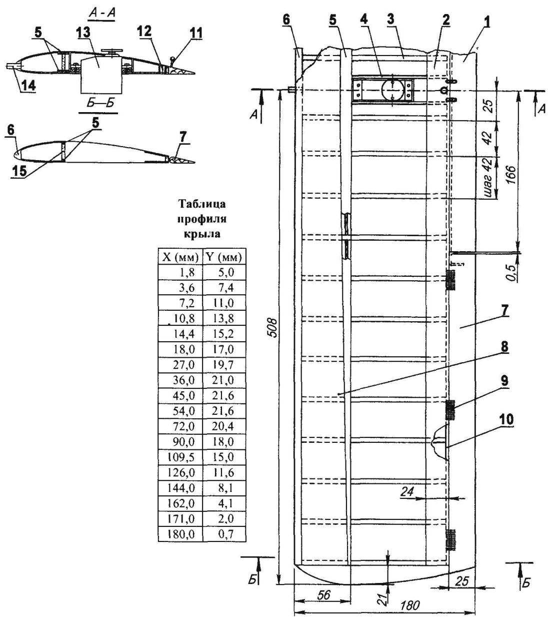
The wing has an asymmetrical PLANO-convex profile with a relative thickness of 12% with good bearing properties.
Beam flange — pine, of variable cross section: 12×3 mm to the root of the wing and 3×3 mm at the end. The wall of the spar is balsa, plate thickness 3 mm. the balsa made From the anterior and posterior edges of the wing and Aileron fairing in the Central part of the wing Balsa veneer are also the forehead of the wing and the back part of it.
Ribs are cut from foam stamps PS-100. This technology has been mentioned many times in “M-K”, however, the material for beginners radiobilogical it’s worth sharing again. First, according to the table control section of the wing, made two templates corresponding to the profile of the wing, then use a tool consisting of stanochek luchkovoj saws and nichrome wire, profiled cut blank which is then cut into “slices”-ribs with thickness of 5 mm Central part of the wing covered with balsa veneer with a thickness of 1 mm.
In front of the wing, along the axis of its symmetry, is beech pin-retainer with a diameter of 5 mm, the rear part of the wing attached to the fuselage duralumin screw with thread M5, for which the wing cuts into the dural sleeve with a hole diameter of 5 mm, and in the fuselage — duralumin threaded sleeve with thread M5.
Ailerons — the balsa to each wing is suspended on three hinges-“eight” of nylon thread the lever-torsion bar actuator of the ailerons are made of steel wire with a diameter of 2 mm. servo control the ailerons installed in the Central part of the wing, with the lever-torsion rocking the steering machine is connected by a pair of rods with ferrules-forks.
The horizontal stabilizer is assembled from balsa strips of 5 mm thick on epoxy glue. The Elevator is also balsa, the stabilizer is pivotally it is fastened by three loops-eights of nylon thread. Pylon rudder is made of cut steel wire of diameter 2 mm with one side tapped M2, with the other bent ring with an inner diameter of 2 mm. Mount the horn on the Elevator — with a pair of nuts and two washers.
The wing and horizontal tail upholstered Mylar film according to the standard model of technology — with the use of glue “Moment” and a small plate.
Wing:
1 — filling the rear spar (balsa rail 8×25); 2 — lining (balsa plate s1,2), 3 — rib (foam, plate s5, 24 PCs); 4 — socket under the steering machine (Linden, plate s3); 5 — spar (pine, battens, AC 3×3 section at the wing tips and 3×12 on the axis of symmetry), 6 — the leading edge of the wing (balsa rail 8х13), 7 — Aileron (balsa rail 8×25), 8 — the lining of brow wing (balsa plate s1,2), 9 — loop”vosmerka” (nylon thread), 10 — trailing edge of the wing (balsa rail 3×6); 11 — the lever-torsion bar actuator Aileron (steel, wire EOD Ø2); 12 — bushing screw wing mounting (aluminum ДІ6Т); 13 — servo actuator Aileron, 14—pin fixation wing (beech, rod Ø5), 15 — wall of the spar (balsa plate s3, 2 PCs)
Horizontal tail:
1 — the Elevator (balsa rail 5×30), 2 — loop-“eight” (nylon thread), 3 — trailing edge (balsa rail 5×15); 4 — the Central rib (balsa plate s5), 5 — the leading edge (balsa rail 5×20), 6,7,8 — rib (balsa rail 5×6); 9 — ending (balsa rail 5×20)
The foam elements are processed first cloth, then covered with one-component parquet varnish thus Primed surface painted with enamel.
In the manufacturing process is regularly checked alignment of the model and corrected if necessary relief items (in extreme case it is possible to weight the front or rear part of the model).
Before flights are finalized alignment. For this curb model mounted on a stand with two triangular supports of the vertices of these triangles should be placed on the wing, near the root ribs by Moving the model forward or backward, seeking equilibrium. If everything is assembled correctly, the center of gravity must lie on the line 25 — 30 percent of the chord of the wing. Note that the front alignment will not raise the nose of the model when landing, and the back will make it unstable.
Before posting the model in the first flight, practice on a simulator, which will make the model itself. Wait for windy weather and hang the unit on a solid filament so that it was in the horizontal plane, nose into the wind by Manipulating the elevators and ailerons, learn to parry rolls, and also enter the device in a “dive” or “pitch up” When you bring your actions to manage model to perfection, send it in flight. First, start the engine and adjust it Then set the camera head to the wind and release it. When the speed model of separation (when she starts to jump and hang in the air) gradually take the Elevator “on yourself” so that the climb took place under a small angle do not forget to parry rolls.
After a set of machine height of about 50 m, try to make a classic “box” — four turn 90 degrees with subsequent planting. To implement the rotation model is introduced into the roll to 45 degrees and at the same time take the handle “on itself” — the model enters the turn After the turn the Elevator is transferred to the neutral and the model is derived from the roll.
If you have correctly completed all four of the turn, then after the final bend of the unit you have, as in the takeoff, is to fly against the wind Because the model has no control of operation of the engine, the flight duration is determined by the amount of fuel in the tank During test runs, measure time and fuel when flying try to keep to the end time of engine operation, the model flew into the wind When you start running in the motor, turn the unit on planning, and when they reach a height of about one meter, switch to horizontal flight, the Next stage is the conditioning when the model gradually loses speed until landing. The angle of attack should be gradually increased. Touch the ground the wheels should ensure at the beginning of parachuting.
I. ZHUKOV
Recommend to read
 MOWS KNIFE
If you have a "no" trimmer, it will not break the neighbor... So, to paraphrase a famous song, you can start the story about the problems with manual lawn electromobility. Most of the... LIGHT SEMICONDUCTORS
In 1907, English engineer Round, who worked at the world famous Marconi laboratory, accidentally noticed that running the detector around a point of contact there is a glow. Also...
